This is simply a descriptive name, typically a common name used for the system.
Diagram
Type
xs:string
Properties
content:
simple
minOccurs:
0
maxOccurs:
1
Source
<xs:element name="Name" type="xs:string" minOccurs="0" maxOccurs="1"><xs:annotation><xs:documentation>This is simply a descriptive name, typically a common name used for the system.</xs:documentation></xs:annotation></xs:element>
Place for user to include additional notes/description of the system.
Diagram
Type
xs:string
Properties
content:
simple
minOccurs:
0
maxOccurs:
1
Source
<xs:element name="Description" type="xs:string" minOccurs="0" maxOccurs="1"><xs:annotation><xs:documentation>Place for user to include additional notes/description of the system.</xs:documentation></xs:annotation></xs:element>
The fluid transported by the distribution system. It may be useful to also indicate the specific gravity of the fluid if it is not a common one.Examples:AirWaterGlycolOil, specific gravity = 0.8Heat Transfer Fluid
Diagram
Type
xs:string
Properties
content:
simple
minOccurs:
0
maxOccurs:
1
Source
<xs:element name="FluidTransported" type="xs:string" minOccurs="0" maxOccurs="1"><xs:annotation><xs:documentation>The fluid transported by the distribution system. It may be useful to also indicate the specific gravity of the fluid if it is not a common one. Examples: Air Water Glycol Oil, specific gravity = 0.8 Heat Transfer Fluid</xs:documentation></xs:annotation></xs:element>
<xs:element name="PrimeMover" type="PrimeMoverSystemType" minOccurs="0" maxOccurs="unbounded"><xs:annotation><xs:documentation>Any pump or fan that drives the fluid - causes it to flow.</xs:documentation></xs:annotation></xs:element>
This is simply a descriptive name, typically a common name used for the system.
Diagram
Type
xs:string
Properties
content:
simple
minOccurs:
0
maxOccurs:
1
Source
<xs:element name="Name" type="xs:string" minOccurs="0" maxOccurs="1"><xs:annotation><xs:documentation>This is simply a descriptive name, typically a common name used for the system.</xs:documentation></xs:annotation></xs:element>
Place for user to include additional notes/description of the system.
Diagram
Type
xs:string
Properties
content:
simple
minOccurs:
0
maxOccurs:
1
Source
<xs:element name="Description" type="xs:string" minOccurs="0" maxOccurs="1"><xs:annotation><xs:documentation>Place for user to include additional notes/description of the system.</xs:documentation></xs:annotation></xs:element>
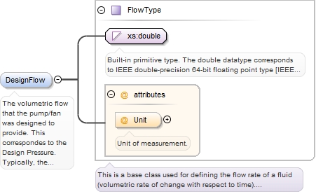
The volumetric flow that the pump/fan was designed to provide. This correspondes to the Design Pressure.

Typically, the design pressure and design flow represent the maximum efficiency point on the manufacturer fan/pump curve. Typically, this is not the maximum flow that the device can provide.
<xs:element name="DesignFlow" type="FlowType" minOccurs="0" maxOccurs="1"><xs:annotation><xs:documentation>The volumetric flow that the pump/fan was designed to provide. This correspondes to the Design Pressure. Typically, the design pressure and design flow represent the maximum efficiency point on the manufacturer fan/pump curve. Typically, this is not the maximum flow that the device can provide.</xs:documentation></xs:annotation></xs:element>
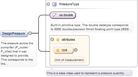
The pressure across the pump/fan (P_outlet - P_inlet) that it was designed to provide. This corresponds to the the Design Flow.

Typically, the design pressure and design flow represent the maximum efficiency point on the manufacturer fan/pump curve.  Typically, this is not the maximum pressure across the device.
<xs:element name="DesignPressure" type="PressureType" minOccurs="0" maxOccurs="1"><xs:annotation><xs:documentation>The pressure across the pump/fan (P_outlet - P_inlet) that it was designed to provide. This corresponds to the the Design Flow. Typically, the design pressure and design flow represent the maximum efficiency point on the manufacturer fan/pump curve. Typically, this is not the maximum pressure across the device.</xs:documentation></xs:annotation></xs:element>
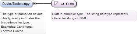
The type of pump/fan device. This typically indicates the blade/impeller type.Examples:Centrifugal, Forward CurvedCentrifugal, Backward CurvedCentrifugal, Radial BladeCentrifugal, AirfoilCentrifugal, PlenumAxial, PropellerAxial, Turbine
Diagram
Type
xs:string
Properties
content:
simple
minOccurs:
0
maxOccurs:
unbounded
Source
<xs:element name="DeviceTechnology" type="xs:string" minOccurs="0" maxOccurs="unbounded"><xs:annotation><xs:documentation>The type of pump/fan device. This typically indicates the blade/impeller type. Examples: Centrifugal, Forward Curved Centrifugal, Backward Curved Centrifugal, Radial Blade Centrifugal, Airfoil Centrifugal, Plenum Axial, Propeller Axial, Turbine</xs:documentation></xs:annotation></xs:element>
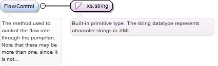
The method used to control the flow rate through the pump/fan. Note that there may be more than one, since it is not uncommon (though somewhat inefficient) to find a VFD and throttle used.Examples:Valve-Manual/AutomaticDamper-Manual/AutomaticVariable Speed Variable Pitch BladeInlet Guide VaneOutlet Damper
Diagram
Type
xs:string
Properties
content:
simple
minOccurs:
0
maxOccurs:
unbounded
Source
<xs:element name="FlowControl" type="xs:string" minOccurs="0" maxOccurs="unbounded"><xs:annotation><xs:documentation>The method used to control the flow rate through the pump/fan. Note that there may be more than one, since it is not uncommon (though somewhat inefficient) to find a VFD and throttle used. Examples: Valve-Manual/Automatic Damper-Manual/Automatic Variable Speed Variable Pitch Blade Inlet Guide Vane Outlet Damper</xs:documentation></xs:annotation></xs:element>
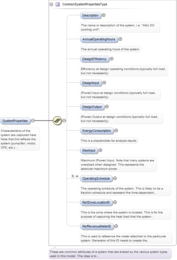
Characteristics of the system are captured here. Note that this reflects the system (pump/fan, motor, VFD, etc.). Properties of the individual components may be captured in equipment attributes.
<xs:element name="SystemProperties" type="CommonSystemPropertiesType" minOccurs="0" maxOccurs="1"><xs:annotation><xs:documentation>Characteristics of the system are captured here. Note that this reflects the system (pump/fan, motor, VFD, etc.). Properties of the individual components may be captured in equipment attributes.</xs:documentation></xs:annotation></xs:element>
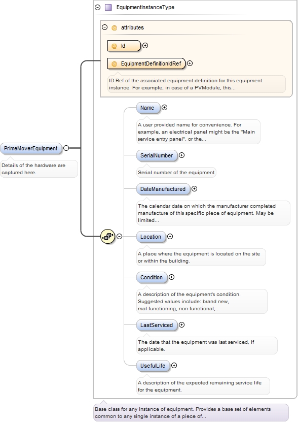
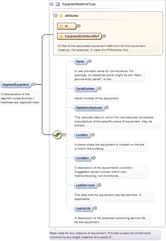
ID Ref of the associated equipment definition for this equipment instance. For example, in case of a PVModule, this would be the ID of the PvModuleDefinition element that describes this particular PV module instance.
<xs:element name="PrimeMoverEquipment" type="EquipmentInstanceType" minOccurs="0" maxOccurs="unbounded"><xs:annotation><xs:documentation>Details of the hardware are captured here.</xs:documentation></xs:annotation></xs:element>
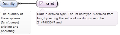
The quantity of these systems (fans/pumps) existing and operating.
Diagram
Type
xs:int
Properties
content:
simple
minOccurs:
0
maxOccurs:
1
Source
<xs:element name="Quantity" type="xs:int" minOccurs="0" maxOccurs="1"><xs:annotation><xs:documentation>The quantity of these systems (fans/pumps) existing and operating.</xs:documentation></xs:annotation></xs:element>
<xs:element maxOccurs="unbounded" minOccurs="0" name="Segment" type="DistributionSegmentType"><xs:annotation><xs:documentation>A segment of the vessel (pipe, duct, etc.) that contains and transports the fluid.</xs:documentation></xs:annotation></xs:element>
This is simply a descriptive name, typically a common name used for the system.
Diagram
Type
xs:string
Properties
content:
simple
minOccurs:
0
maxOccurs:
1
Source
<xs:element name="Name" type="xs:string" minOccurs="0" maxOccurs="1"><xs:annotation><xs:documentation>This is simply a descriptive name, typically a common name used for the system.</xs:documentation></xs:annotation></xs:element>
Place for user to include additional notes and description of this segment.If a complex system of segments is to be defined, it would be useful to describe the system here.Other quantities or features may also be described here, such as the loss coefficient (i.e. pressure drop due to fluid friction).
Diagram
Type
xs:string
Properties
content:
simple
minOccurs:
0
maxOccurs:
1
Source
<xs:element name="Description" type="xs:string" minOccurs="0" maxOccurs="1"><xs:annotation><xs:documentation>Place for user to include additional notes and description of this segment. If a complex system of segments is to be defined, it would be useful to describe the system here. Other quantities or features may also be described here, such as the loss coefficient (i.e. pressure drop due to fluid friction).</xs:documentation></xs:annotation></xs:element>
ID Ref of the associated equipment definition for this equipment instance. For example, in case of a PVModule, this would be the ID of the PvModuleDefinition element that describes this particular PV module instance.
<xs:element name="SegmentEquipment" type="EquipmentInstanceType" minOccurs="0" maxOccurs="unbounded"><xs:annotation><xs:documentation>Characteristics of the segment (pipe/duct/etc.) hardware are captured here.</xs:documentation></xs:annotation></xs:element>
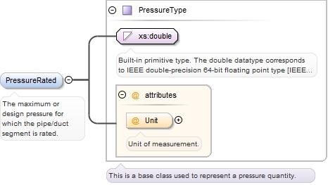
<xs:element name="PressureRated" type="PressureType" minOccurs="0" maxOccurs="1"><xs:annotation><xs:documentation>The maximum or design pressure for which the pipe/duct segment is rated.</xs:documentation></xs:annotation></xs:element>
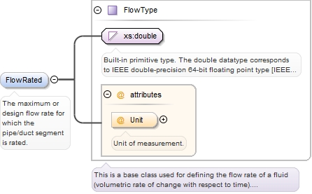
<xs:element name="FlowRated" type="FlowType" minOccurs="0" maxOccurs="1"><xs:annotation><xs:documentation>The maximum or design flow rate for which the pipe/duct segment is rated.</xs:documentation></xs:annotation></xs:element>
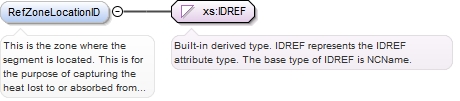
This is the zone where the segment is located. This is for the purpose of capturing the heat lost to or absorbed from the environment by the fluid in the segment.
Diagram
Type
xs:IDREF
Properties
content:
simple
minOccurs:
0
maxOccurs:
1
Source
<xs:element maxOccurs="1" minOccurs="0" name="RefZoneLocationID" type="xs:IDREF"><xs:annotation><xs:documentation>This is the zone where the segment is located. This is for the purpose of capturing the heat lost to or absorbed from the environment by the fluid in the segment.</xs:documentation></xs:annotation></xs:element>
Element DistributionSystem
Namespace
http://www.iepmodel.net
Annotations
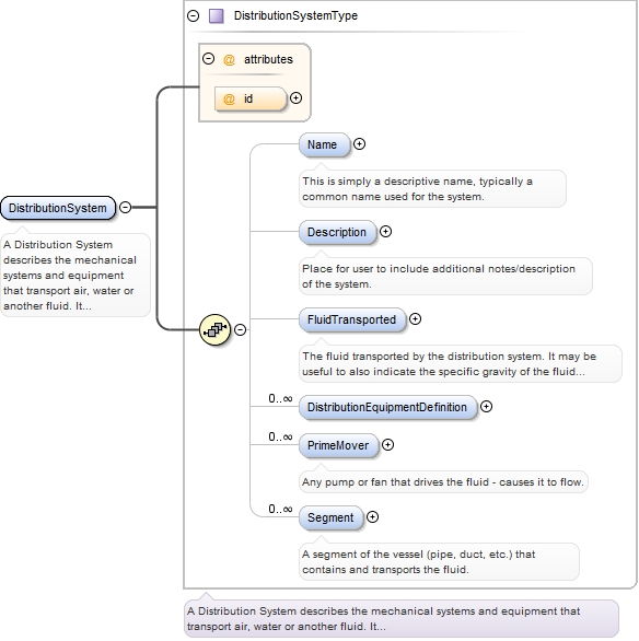
A Distribution System describes the mechanical systems and equipment that transport air, water or another fluid. It consists of two components: Prime Mover (pump or fan) and Segment.A Distribution System (optionally) consists of one or many Prime Movers, which is a pump or fan that causes the fluid to flow. The Prime Mover has System and Equipment properties.A Distribution System (optionally) consists of one or many Segments, which is a duct or pipe that transports the fluid. The Segment has Equipment properties in addition to leakage and insulation properties (referenced from the Building schema).The Distribution Systems was chosen to stand alone because of how the other systems interact with it and because on distribution system may serve multiple purposes. It is be referenced by other systems such as an HVAC or WaterHeating system that interact with it.A Distribution System (particularly air or water) may be referenced by an HVAC system in one of three ways. A Distribution System may be referenced as the method of delivery of conditioning from the HVAC system (i.e. the ducting or piping that delivers conditioning). Alternatively, a Distribution System may be referenced as the source of heat or cold (fluid to reject heat to) for a Heating or Cooling system, respectively.Note that the Distribution System itself does not instance System Properties. A distribution system can only consume energy through its prime mover and thermal transfer. The Prime Mover object instances System Properties. Thermal transfer to or from the fluid through its segments will affect the system(s) that are connected to (reference) it (such as a Hot Water Heating or HVAC system). Thus, the thermal energy transferred through the segment surface should be captured by the zone in which the segment is located and the systems that reference it.Example 1. A water DistributionSystem may serve both space heating as well as domestic hot water for kitchen and bathroom fixtures (i.e. dishwasher, shower). Systems that may reference this DistributionSystem include: a WaterHeating system, a grey-water HeatRecovery system and an HVACSystem.Example 2An air DistributionSystem may consist of supply and return ducting and a supply fan. An HVACSystem such as a furnace or air-source heat-pump would reference the DistributionSystem (through its DeliveryMethod element). Example 3A Whole house fan would be modeled as an HVAC system with a DeliveryMethod that references a Distribution System. The Distribution System may include segments (inlet and exhaust ducting) and a fan (Prime Mover). The Ventilation properties in HVAC would further describe the rate of air exchange with outside. The zone(s) referencing the HVAC system would specify the temperature setpoint schedule and any additional thermal loads. Alternatively, if the fan is controlled by a time schedule, rather than temperature schedule, the schedule may defined in the Prime Mover system properties. Then, no HVAC system needs to be defined.Example 4A bathroom or kitchen exhaust fan may be modeled as a Distribution System with just a Prime Mover (segments optional). The schedule in the System Properties of the Primer Mover may define the operating schedule of the fan.
<xs:element name="DistributionSystem" type="DistributionSystemType"><xs:annotation><xs:documentation>A Distribution System describes the mechanical systems and equipment that transport air, water or another fluid. It consists of two components: Prime Mover (pump or fan) and Segment. A Distribution System (optionally) consists of one or many Prime Movers, which is a pump or fan that causes the fluid to flow. The Prime Mover has System and Equipment properties. A Distribution System (optionally) consists of one or many Segments, which is a duct or pipe that transports the fluid. The Segment has Equipment properties in addition to leakage and insulation properties (referenced from the Building schema). The Distribution Systems was chosen to stand alone because of how the other systems interact with it and because on distribution system may serve multiple purposes. It is be referenced by other systems such as an HVAC or WaterHeating system that interact with it. A Distribution System (particularly air or water) may be referenced by an HVAC system in one of three ways. A Distribution System may be referenced as the method of delivery of conditioning from the HVAC system (i.e. the ducting or piping that delivers conditioning). Alternatively, a Distribution System may be referenced as the source of heat or cold (fluid to reject heat to) for a Heating or Cooling system, respectively. Note that the Distribution System itself does not instance System Properties. A distribution system can only consume energy through its prime mover and thermal transfer. The Prime Mover object instances System Properties. Thermal transfer to or from the fluid through its segments will affect the system(s) that are connected to (reference) it (such as a Hot Water Heating or HVAC system). Thus, the thermal energy transferred through the segment surface should be captured by the zone in which the segment is located and the systems that reference it. Example 1. A water DistributionSystem may serve both space heating as well as domestic hot water for kitchen and bathroom fixtures (i.e. dishwasher, shower). Systems that may reference this DistributionSystem include: a WaterHeating system, a grey-water HeatRecovery system and an HVACSystem. Example 2 An air DistributionSystem may consist of supply and return ducting and a supply fan. An HVACSystem such as a furnace or air-source heat-pump would reference the DistributionSystem (through its DeliveryMethod element). Example 3 A Whole house fan would be modeled as an HVAC system with a DeliveryMethod that references a Distribution System. The Distribution System may include segments (inlet and exhaust ducting) and a fan (Prime Mover). The Ventilation properties in HVAC would further describe the rate of air exchange with outside. The zone(s) referencing the HVAC system would specify the temperature setpoint schedule and any additional thermal loads. Alternatively, if the fan is controlled by a time schedule, rather than temperature schedule, the schedule may defined in the Prime Mover system properties. Then, no HVAC system needs to be defined. Example 4 A bathroom or kitchen exhaust fan may be modeled as a Distribution System with just a Prime Mover (segments optional). The schedule in the System Properties of the Primer Mover may define the operating schedule of the fan.</xs:documentation></xs:annotation></xs:element>
Complex Type DistributionSystemType
Namespace
http://www.iepmodel.net
Annotations
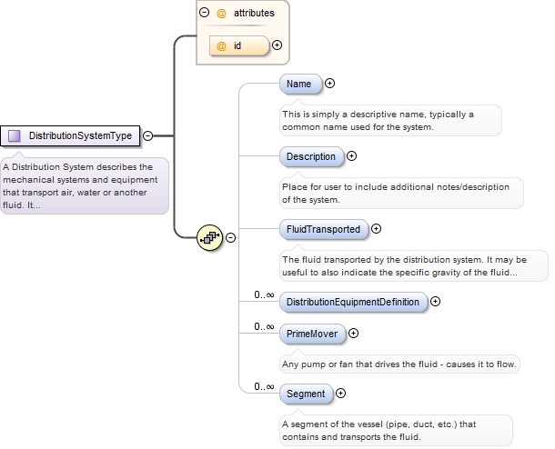
A Distribution System describes the mechanical systems and equipment that transport air, water or another fluid. It consists of two components: Prime Mover (pump or fan) and Segment.A Distribution System (optionally) consists of one or many Prime Movers, which are pumps or fans that causes the fluid to flow. The Prime Mover has System and Equipment properties.A Distribution System (optionally) consists of one or many Segments, which is a duct or pipe that transports the fluid. The Segment has Equipment properties in addition to leakage and insulation properties (referenced from the Building schema).The Distribution Systems was chosen to stand alone because of how the other systems interact with it and because one distribution system may serve multiple purposes. It is be referenced by other systems such as an HVAC or WaterHeating system that interact with it.A Distribution System (particularly air or water) may be referenced by an HVAC system in one of three ways. A Distribution System may be referenced as the method of delivery of conditioning from the HVAC system (i.e. the ducting or piping that delivers conditioning). Alternatively, a Distribution System may be referenced as the source of heat or cold (fluid to reject heat to) for a Heating or Cooling system, respectively.Note that the Distribution System itself does not instance System Properties. A distribution system can only consume energy through its prime mover and thermal transfer with the environment. The Prime Mover object instances System Properties. Thermal transfer to or from the fluid through its segments will affect the system(s) that are connected to (reference) it (such as a Hot Water Heating or HVAC system). Thus, the thermal energy transferred through the segment surface should be captured by the zone in which the segment is located and the systems that reference it.Example 1. A water DistributionSystem may serve both space heating as well as domestic hot water for kitchen and bathroom fixtures (i.e. dishwasher, shower). Systems that may reference this DistributionSystem include: a WaterHeating system, a grey-water HeatRecovery system and an HVACSystem.Example 2.An air DistributionSystem may consist of supply and return ducting and a supply fan. An HVACSystem such as a furnace or air-source heat-pump would reference the DistributionSystem (through its DeliveryMethod element). Example 3.A whole-house fan would be modeled as an HVAC system with a DeliveryMethod that references a Distribution System. The Distribution System may include segments (inlet and exhaust ducting) and a fan (Prime Mover). The Ventilation properties in HVAC would further describe the rate of air exchange with outside. The zone(s) referencing the HVAC system would specify the temperature setpoint schedule and any additional thermal loads. Alternatively, if the fan is controlled by a time schedule, rather than temperature schedule, the schedule may defined in the Prime Mover system properties. Then, no HVAC system needs to be defined.Example 4.A bathroom or kitchen exhaust fan may be modeled as a Distribution System with just a Prime Mover (segments optional). The schedule in the System Properties of the Primer Mover may define the operating schedule of the fan.
<xs:complexType name="DistributionSystemType"><xs:annotation><xs:documentation>A Distribution System describes the mechanical systems and equipment that transport air, water or another fluid. It consists of two components: Prime Mover (pump or fan) and Segment. A Distribution System (optionally) consists of one or many Prime Movers, which are pumps or fans that causes the fluid to flow. The Prime Mover has System and Equipment properties. A Distribution System (optionally) consists of one or many Segments, which is a duct or pipe that transports the fluid. The Segment has Equipment properties in addition to leakage and insulation properties (referenced from the Building schema). The Distribution Systems was chosen to stand alone because of how the other systems interact with it and because one distribution system may serve multiple purposes. It is be referenced by other systems such as an HVAC or WaterHeating system that interact with it. A Distribution System (particularly air or water) may be referenced by an HVAC system in one of three ways. A Distribution System may be referenced as the method of delivery of conditioning from the HVAC system (i.e. the ducting or piping that delivers conditioning). Alternatively, a Distribution System may be referenced as the source of heat or cold (fluid to reject heat to) for a Heating or Cooling system, respectively. Note that the Distribution System itself does not instance System Properties. A distribution system can only consume energy through its prime mover and thermal transfer with the environment. The Prime Mover object instances System Properties. Thermal transfer to or from the fluid through its segments will affect the system(s) that are connected to (reference) it (such as a Hot Water Heating or HVAC system). Thus, the thermal energy transferred through the segment surface should be captured by the zone in which the segment is located and the systems that reference it. Example 1. A water DistributionSystem may serve both space heating as well as domestic hot water for kitchen and bathroom fixtures (i.e. dishwasher, shower). Systems that may reference this DistributionSystem include: a WaterHeating system, a grey-water HeatRecovery system and an HVACSystem. Example 2. An air DistributionSystem may consist of supply and return ducting and a supply fan. An HVACSystem such as a furnace or air-source heat-pump would reference the DistributionSystem (through its DeliveryMethod element). Example 3. A whole-house fan would be modeled as an HVAC system with a DeliveryMethod that references a Distribution System. The Distribution System may include segments (inlet and exhaust ducting) and a fan (Prime Mover). The Ventilation properties in HVAC would further describe the rate of air exchange with outside. The zone(s) referencing the HVAC system would specify the temperature setpoint schedule and any additional thermal loads. Alternatively, if the fan is controlled by a time schedule, rather than temperature schedule, the schedule may defined in the Prime Mover system properties. Then, no HVAC system needs to be defined. Example 4. A bathroom or kitchen exhaust fan may be modeled as a Distribution System with just a Prime Mover (segments optional). The schedule in the System Properties of the Primer Mover may define the operating schedule of the fan.</xs:documentation></xs:annotation><xs:sequence><xs:element name="Name" type="xs:string" minOccurs="0" maxOccurs="1"><xs:annotation><xs:documentation>This is simply a descriptive name, typically a common name used for the system.</xs:documentation></xs:annotation></xs:element><xs:element name="Description" type="xs:string" minOccurs="0" maxOccurs="1"><xs:annotation><xs:documentation>Place for user to include additional notes/description of the system.</xs:documentation></xs:annotation></xs:element><xs:element name="FluidTransported" type="xs:string" minOccurs="0" maxOccurs="1"><xs:annotation><xs:documentation>The fluid transported by the distribution system. It may be useful to also indicate the specific gravity of the fluid if it is not a common one. Examples: Air Water Glycol Oil, specific gravity = 0.8 Heat Transfer Fluid</xs:documentation></xs:annotation></xs:element><xs:element maxOccurs="unbounded" minOccurs="0" name="DistributionEquipmentDefinition" type="EquipmentDefinitionType"/><xs:element name="PrimeMover" type="PrimeMoverSystemType" minOccurs="0" maxOccurs="unbounded"><xs:annotation><xs:documentation>Any pump or fan that drives the fluid - causes it to flow.</xs:documentation></xs:annotation></xs:element><xs:element maxOccurs="unbounded" minOccurs="0" name="Segment" type="DistributionSegmentType"><xs:annotation><xs:documentation>A segment of the vessel (pipe, duct, etc.) that contains and transports the fluid.</xs:documentation></xs:annotation></xs:element></xs:sequence><xs:attribute name="id" type="xs:ID"/></xs:complexType>
Complex Type PrimeMoverSystemType
Namespace
http://www.iepmodel.net
Annotations
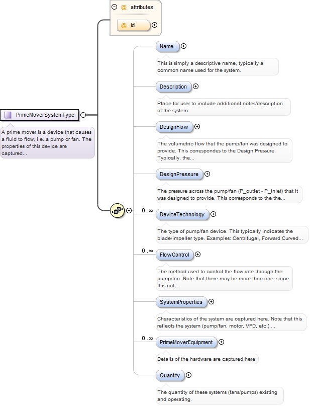
A prime mover is a device that causes a fluid to flow, i.e. a pump or fan. The properties of this device are captured here. This object includes System and Equipment properties.
<xs:complexType name="PrimeMoverSystemType"><xs:annotation><xs:documentation>A prime mover is a device that causes a fluid to flow, i.e. a pump or fan. The properties of this device are captured here. This object includes System and Equipment properties.</xs:documentation></xs:annotation><xs:sequence><xs:element name="Name" type="xs:string" minOccurs="0" maxOccurs="1"><xs:annotation><xs:documentation>This is simply a descriptive name, typically a common name used for the system.</xs:documentation></xs:annotation></xs:element><xs:element name="Description" type="xs:string" minOccurs="0" maxOccurs="1"><xs:annotation><xs:documentation>Place for user to include additional notes/description of the system.</xs:documentation></xs:annotation></xs:element><xs:element name="DesignFlow" type="FlowType" minOccurs="0" maxOccurs="1"><xs:annotation><xs:documentation>The volumetric flow that the pump/fan was designed to provide. This correspondes to the Design Pressure. Typically, the design pressure and design flow represent the maximum efficiency point on the manufacturer fan/pump curve. Typically, this is not the maximum flow that the device can provide.</xs:documentation></xs:annotation></xs:element><xs:element name="DesignPressure" type="PressureType" minOccurs="0" maxOccurs="1"><xs:annotation><xs:documentation>The pressure across the pump/fan (P_outlet - P_inlet) that it was designed to provide. This corresponds to the the Design Flow. Typically, the design pressure and design flow represent the maximum efficiency point on the manufacturer fan/pump curve. Typically, this is not the maximum pressure across the device.</xs:documentation></xs:annotation></xs:element><xs:element name="DeviceTechnology" type="xs:string" minOccurs="0" maxOccurs="unbounded"><xs:annotation><xs:documentation>The type of pump/fan device. This typically indicates the blade/impeller type. Examples: Centrifugal, Forward Curved Centrifugal, Backward Curved Centrifugal, Radial Blade Centrifugal, Airfoil Centrifugal, Plenum Axial, Propeller Axial, Turbine</xs:documentation></xs:annotation></xs:element><xs:element name="FlowControl" type="xs:string" minOccurs="0" maxOccurs="unbounded"><xs:annotation><xs:documentation>The method used to control the flow rate through the pump/fan. Note that there may be more than one, since it is not uncommon (though somewhat inefficient) to find a VFD and throttle used. Examples: Valve-Manual/Automatic Damper-Manual/Automatic Variable Speed Variable Pitch Blade Inlet Guide Vane Outlet Damper</xs:documentation></xs:annotation></xs:element><xs:element name="SystemProperties" type="CommonSystemPropertiesType" minOccurs="0" maxOccurs="1"><xs:annotation><xs:documentation>Characteristics of the system are captured here. Note that this reflects the system (pump/fan, motor, VFD, etc.). Properties of the individual components may be captured in equipment attributes.</xs:documentation></xs:annotation></xs:element><xs:element name="PrimeMoverEquipment" type="EquipmentInstanceType" minOccurs="0" maxOccurs="unbounded"><xs:annotation><xs:documentation>Details of the hardware are captured here.</xs:documentation></xs:annotation></xs:element><xs:element name="Quantity" type="xs:int" minOccurs="0" maxOccurs="1"><xs:annotation><xs:documentation>The quantity of these systems (fans/pumps) existing and operating.</xs:documentation></xs:annotation></xs:element></xs:sequence><xs:attribute name="id" type="xs:ID"/></xs:complexType>
Complex Type DistributionSegmentType
Namespace
http://www.iepmodel.net
Annotations
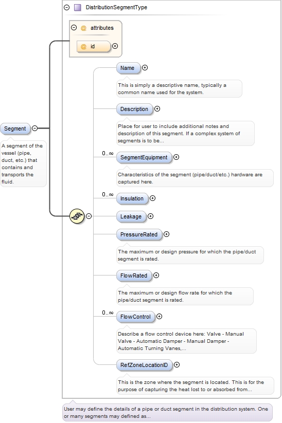
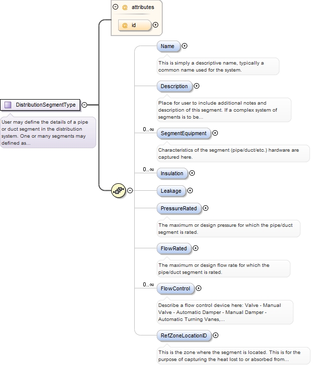
User may define the details of a pipe or duct segment in the distribution system.One or many segments may defined as necessary to describe the system in detail.
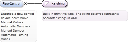
<xs:complexType name="DistributionSegmentType"><xs:annotation><xs:documentation>User may define the details of a pipe or duct segment in the distribution system. One or many segments may defined as necessary to describe the system in detail.</xs:documentation></xs:annotation><xs:sequence><xs:element name="Name" type="xs:string" minOccurs="0" maxOccurs="1"><xs:annotation><xs:documentation>This is simply a descriptive name, typically a common name used for the system.</xs:documentation></xs:annotation></xs:element><xs:element name="Description" type="xs:string" minOccurs="0" maxOccurs="1"><xs:annotation><xs:documentation>Place for user to include additional notes and description of this segment. If a complex system of segments is to be defined, it would be useful to describe the system here. Other quantities or features may also be described here, such as the loss coefficient (i.e. pressure drop due to fluid friction).</xs:documentation></xs:annotation></xs:element><xs:element name="SegmentEquipment" type="EquipmentInstanceType" minOccurs="0" maxOccurs="unbounded"><xs:annotation><xs:documentation>Characteristics of the segment (pipe/duct/etc.) hardware are captured here.</xs:documentation></xs:annotation></xs:element><xs:element maxOccurs="unbounded" minOccurs="0" name="Insulation" type="InsulationType"/><xs:element minOccurs="0" name="Leakage" type="LeakageType"/><xs:element name="PressureRated" type="PressureType" minOccurs="0" maxOccurs="1"><xs:annotation><xs:documentation>The maximum or design pressure for which the pipe/duct segment is rated.</xs:documentation></xs:annotation></xs:element><xs:element name="FlowRated" type="FlowType" minOccurs="0" maxOccurs="1"><xs:annotation><xs:documentation>The maximum or design flow rate for which the pipe/duct segment is rated.</xs:documentation></xs:annotation></xs:element><xs:element maxOccurs="unbounded" minOccurs="0" name="FlowControl" type="xs:string"><xs:annotation><xs:documentation>Describe a flow control device here: Valve - Manual Valve - Automatic Damper - Manual Damper - Automatic Turning Vanes, loss coefficient 0.24</xs:documentation></xs:annotation></xs:element><xs:element maxOccurs="1" minOccurs="0" name="RefZoneLocationID" type="xs:IDREF"><xs:annotation><xs:documentation>This is the zone where the segment is located. This is for the purpose of capturing the heat lost to or absorbed from the environment by the fluid in the segment.</xs:documentation></xs:annotation></xs:element></xs:sequence><xs:attribute name="id" type="xs:ID"/></xs:complexType>