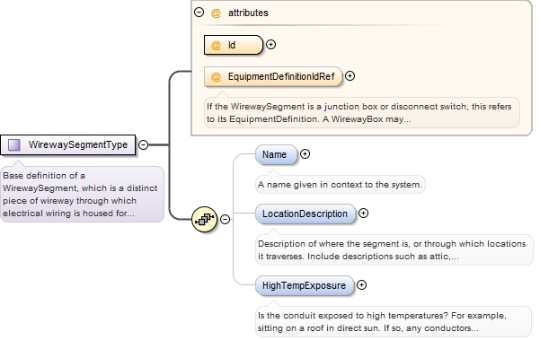
<xs:element name="Name" type="xs:string" minOccurs="0"><xs:annotation><xs:documentation>A name given in context to the system.</xs:documentation></xs:annotation></xs:element>
Description of where the segment is, or through which locations it traverses. Include descriptions such as attic, interior, exterior, roof, or trench.
Diagram
Type
xs:string
Properties
content:
simple
minOccurs:
0
Source
<xs:element minOccurs="0" name="LocationDescription" type="xs:string"><xs:annotation><xs:documentation>Description of where the segment is, or through which locations it traverses. Include descriptions such as attic, interior, exterior, roof, or trench.</xs:documentation></xs:annotation></xs:element>
Is the conduit exposed to high temperatures? For example, sitting on a roof in direct sun. If so, any conductors contained within the segment may have to have their rated current carrying capacity derated.
Diagram
Type
xs:boolean
Properties
content:
simple
minOccurs:
0
maxOccurs:
1
Source
<xs:element name="HighTempExposure" type="xs:boolean" minOccurs="0" maxOccurs="1"><xs:annotation><xs:documentation>Is the conduit exposed to high temperatures? For example, sitting on a roof in direct sun. If so, any conductors contained within the segment may have to have their rated current carrying capacity derated.</xs:documentation></xs:annotation></xs:element>
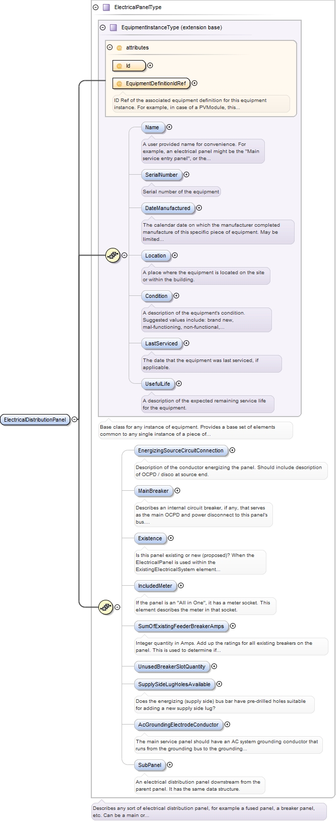
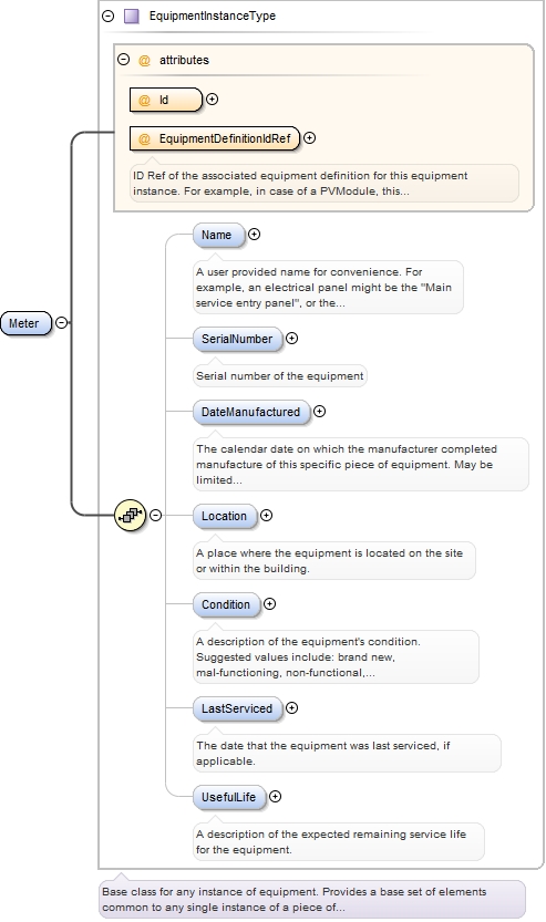
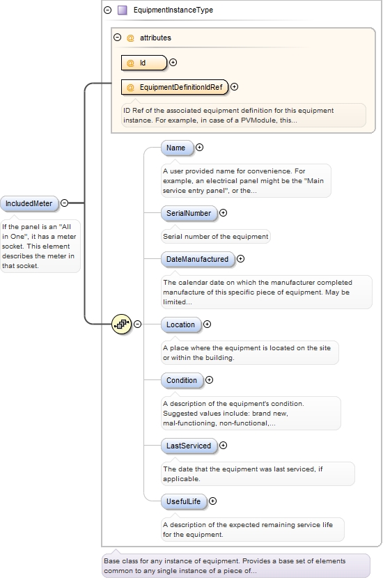
ID Ref of the associated equipment definition for this equipment instance. For example, in case of a PVModule, this would be the ID of the PvModuleDefinition element that describes this particular PV module instance.
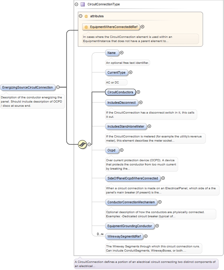
In cases where the CircuitConnection element is used within an EquipmentInstance that does not have a parent element to which the CircuitConnection is assumed to connect, a reference ID can be used to associate this CircuitConnection to another EquipmentInstance elsewhere in a document instance. For example, a PvSystem may have an AcPointOfConnection that uses a new ElectricalPanel as an AC combiner for more than one Inverter. The new electrical panel can be described by an ElectricalPanel element in the PvDesign (which in turn refers to an ElectricalPanelDefinition element).in the AcPointOfConnection's EquipmentWhereConnected element. That ElectricPanel's EnergizingCircuitConnection element may reference another ElectricPanel in an instance of the Project's ExistingElectricalHierarchy element.
Source
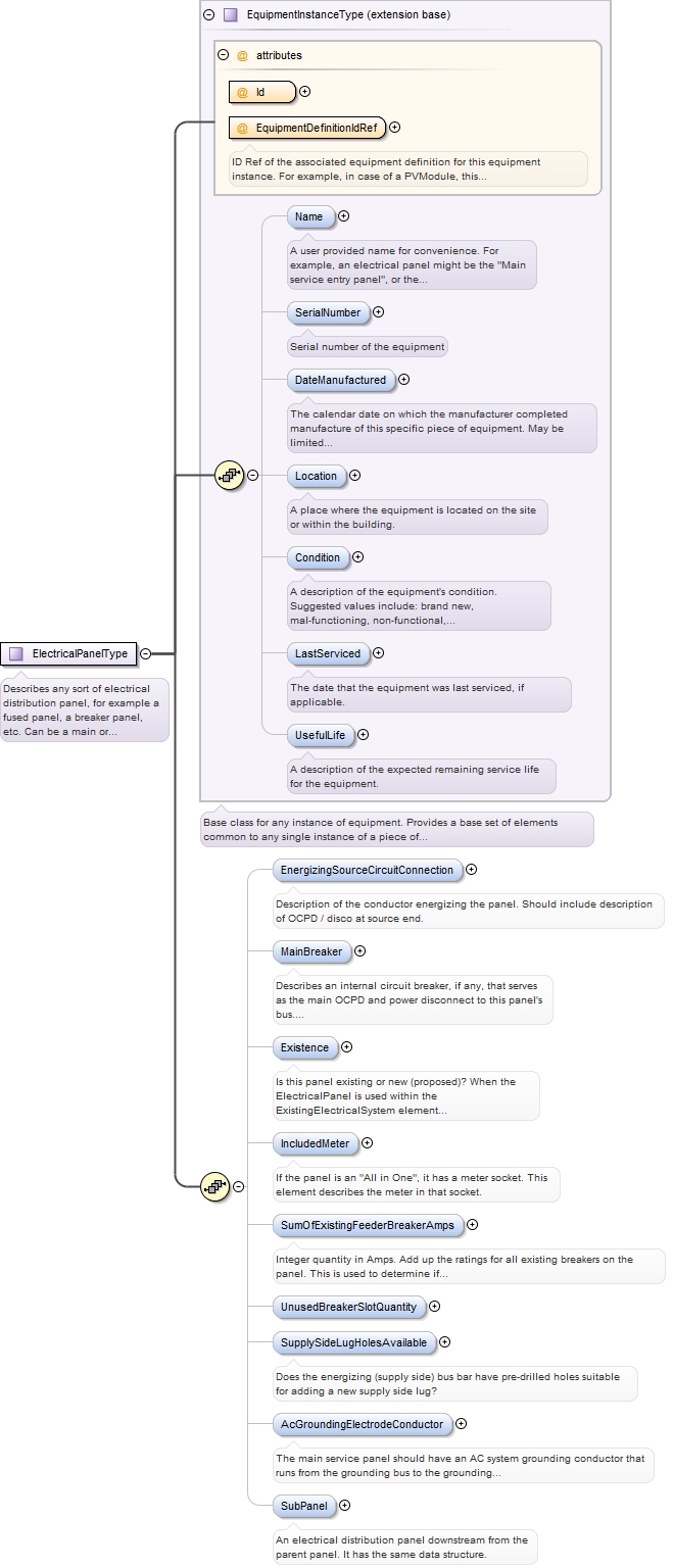
<xs:element minOccurs="0" name="EnergizingSourceCircuitConnection" type="CircuitConnectionType" maxOccurs="1"><xs:annotation><xs:documentation>Description of the conductor energizing the panel. Should include description of OCPD / disco at source end.</xs:documentation></xs:annotation></xs:element>
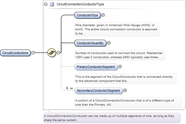
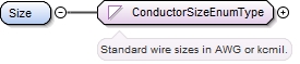
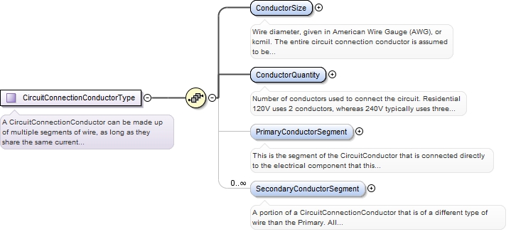
Wire diameter, given in American Wire Gauge (AWG), or kcmil. The entire circuit connection conductor is assumed to be the same size conductor, even if it is physically made up of multiple conductor segments that are different kinds of wire.
<xs:element name="ConductorSize" type="ConductorSizeEnumType"><xs:annotation><xs:documentation>Wire diameter, given in American Wire Gauge (AWG), or kcmil. The entire circuit connection conductor is assumed to be the same size conductor, even if it is physically made up of multiple conductor segments that are different kinds of wire.</xs:documentation></xs:annotation></xs:element>
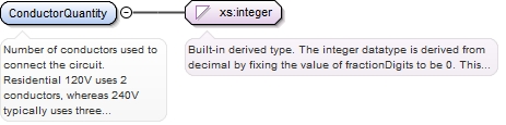
Number of conductors used to connect the circuit. Residential 120V uses 2 conductors, whereas 240V typically uses three conductors, and commercial three phase typically is 4 conductors.
Diagram
Type
xs:integer
Properties
content:
simple
minOccurs:
1
Source
<xs:element minOccurs="1" name="ConductorQuantity" type="xs:integer"><xs:annotation><xs:documentation>Number of conductors used to connect the circuit. Residential 120V uses 2 conductors, whereas 240V typically uses three conductors, and commercial three phase typically is 4 conductors.</xs:documentation></xs:annotation></xs:element>
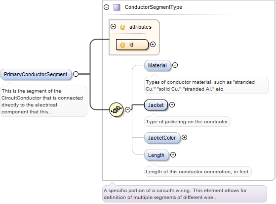
This is the segment of the CircuitConductor that is connected directly to the electrical component that this CircuitConnection belongs to. For example, let's assume that this ConductorSegment is part of a CircuitConnection for a PvString. The PvString typically starts out as USE-2 wire from the PV Modules and may transition to THWN-2 wire once inside a J-box (modeled as a Wireway box in this schema). The USE-2 segment of the conductor is the Primary segment, while the THWN-2 wire is a secondary segment. All CircuitConnectionConductors have a primary segment, only some have any secondary instances. If there are more than one, then the splices made beween them are described by the ConnectsToConductorSegmentId and the WirewaySegmentWhereConnectedId attributes.
<xs:element minOccurs="0" name="PrimaryConductorSegment" type="ConductorSegmentType"><xs:annotation><xs:documentation>This is the segment of the CircuitConductor that is connected directly to the electrical component that this CircuitConnection belongs to. For example, let's assume that this ConductorSegment is part of a CircuitConnection for a PvString. The PvString typically starts out as USE-2 wire from the PV Modules and may transition to THWN-2 wire once inside a J-box (modeled as a Wireway box in this schema). The USE-2 segment of the conductor is the Primary segment, while the THWN-2 wire is a secondary segment. All CircuitConnectionConductors have a primary segment, only some have any secondary instances. If there are more than one, then the splices made beween them are described by the ConnectsToConductorSegmentId and the WirewaySegmentWhereConnectedId attributes.</xs:documentation></xs:annotation></xs:element>
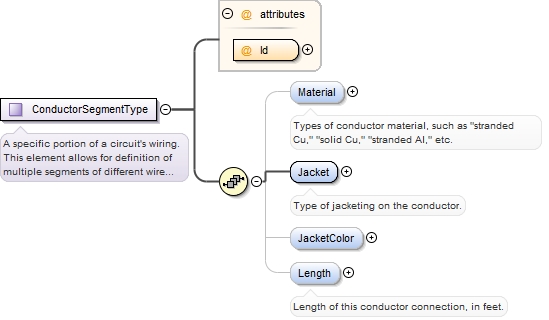
<xs:element minOccurs="1" name="Jacket" type="ConductorJacketEnumType"><xs:annotation><xs:documentation>Type of jacketing on the conductor.</xs:documentation></xs:annotation></xs:element>
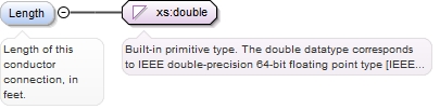
<xs:element name="Length" type="xs:double" minOccurs="0" maxOccurs="1"><xs:annotation><xs:documentation>Length of this conductor connection, in feet.</xs:documentation></xs:annotation></xs:element>
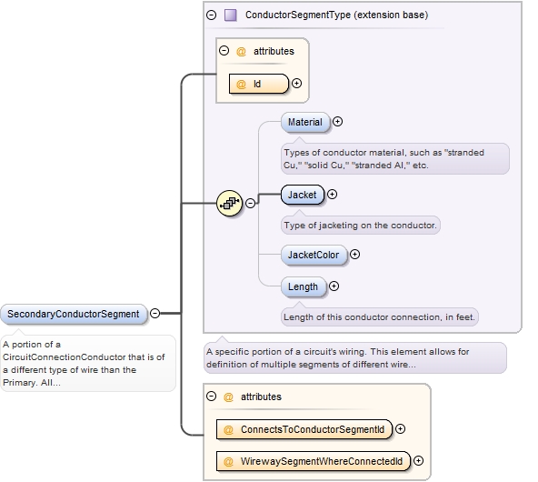
A portion of a CircuitConnectionConductor that is of a different type of wire than the Primary. All CircuitConnectionConductors have a primary segment, only some have any secondary instances. If there are more than one, then the splices made beween them are described by the ConnectsToConductorSegmentId and the WirewaySegmentWhereConnectedId attributes.
<xs:element maxOccurs="unbounded" minOccurs="0" name="SecondaryConductorSegment"><xs:annotation><xs:documentation>A portion of a CircuitConnectionConductor that is of a different type of wire than the Primary. All CircuitConnectionConductors have a primary segment, only some have any secondary instances. If there are more than one, then the splices made beween them are described by the ConnectsToConductorSegmentId and the WirewaySegmentWhereConnectedId attributes.</xs:documentation></xs:annotation><xs:complexType><xs:complexContent><xs:extension base="ConductorSegmentType"><xs:attribute name="ConnectsToConductorSegmentId" type="xs:IDREF" use="required"/><xs:attribute name="WirewaySegmentWhereConnectedId" type="xs:IDREF" use="required"/></xs:extension></xs:complexContent></xs:complexType></xs:element>
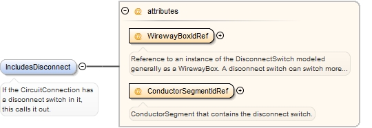
Reference to an instance of the DisconnectSwitch modeled generally as a WirewayBox. A disconnect switch can switch more than one CircuitConnection, so it is defined external to the CircuitConnection.
Source
<xs:element minOccurs="0" name="IncludesDisconnect"><xs:annotation><xs:documentation>If the CircuitConnection has a disconnect switch in it, this calls it out.</xs:documentation></xs:annotation><xs:complexType><xs:attribute name="WirewayBoxIdRef" type="xs:IDREF" use="required"><xs:annotation><xs:documentation>Reference to an instance of the DisconnectSwitch modeled generally as a WirewayBox. A disconnect switch can switch more than one CircuitConnection, so it is defined external to the CircuitConnection.</xs:documentation></xs:annotation></xs:attribute><xs:attribute name="ConductorSegmentIdRef" type="xs:IDREF" use="required"><xs:annotation><xs:documentation>ConductorSegment that contains the disconnect switch.</xs:documentation></xs:annotation></xs:attribute></xs:complexType></xs:element>
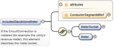
If the CircuitConnection is metered (for example the utility's revenue meter), this element describes the meter socket and meter. The meter and socket are individual entities. The MeterSocket is modeled as a simple WirewayBox.
<xs:element minOccurs="0" name="IncludesStandAloneMeter"><xs:annotation><xs:documentation>If the CircuitConnection is metered (for example the utility's revenue meter), this element describes the meter socket and meter. The meter and socket are individual entities. The MeterSocket is modeled as a simple WirewayBox.</xs:documentation></xs:annotation><xs:complexType><xs:sequence><xs:element name="MeterSocket" type="WirewayBoxType"/><xs:element name="Meter" type="EquipmentInstanceType"/></xs:sequence><xs:attribute name="ConductorSegmentIdRef" type="xs:IDREF"/></xs:complexType></xs:element>
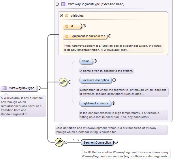
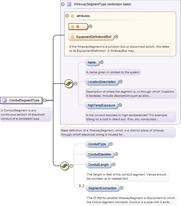
If the WirewaySegment is a junction box or disconnect switch, this refers to its EquipmentDefinition. A WirewayBox may be a pass through where multiple ConduitSegments are combined into a single ConduitSegment for example. A disconnect switch box may also be modeled as a WirewayBox, provided that the circuit(s) involved are simply disoconnected and not combined in any way. DO NOT use WirewayBox to represent a combiner, or distribution panel.
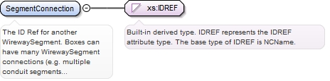
The ID Ref for another WirewaySegment. Boxes can have many WirewaySegment connections (e.g. multiple conduit segments can terminate at a box). Conduit is a pipe with 2 ends, so it has a maximum of two WirewaySegments to which it connects.
Diagram
Type
xs:IDREF
Properties
content:
simple
minOccurs:
1
maxOccurs:
unbounded
Source
<xs:element maxOccurs="unbounded" name="SegmentConnection" type="xs:IDREF" minOccurs="1"><xs:annotation><xs:documentation>The ID Ref for another WirewaySegment. Boxes can have many WirewaySegment connections (e.g. multiple conduit segments can terminate at a box). Conduit is a pipe with 2 ends, so it has a maximum of two WirewaySegments to which it connects.</xs:documentation></xs:annotation></xs:element>
ID Ref of the associated equipment definition for this equipment instance. For example, in case of a PVModule, this would be the ID of the PvModuleDefinition element that describes this particular PV module instance.
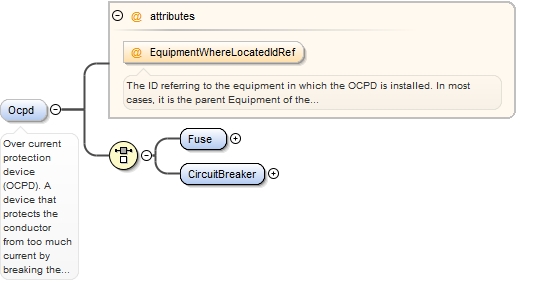
Over current protection device (OCPD). A device that protects the conductor from too much current by breaking the circuit. Fuses and circuit breakers are OCPDs. In this schema, an OCPD is not a piece of equipment, but rather a component within a piece of equipment. It is not necessary to include a mfr and model in most cases, but knowing the type and rating is required.
The ID referring to the equipment in which the OCPD is installed. In most cases, it is the parent Equipment of the CircuitConnection's immediate parent element. For example, if the CircuitConnection is within a StringInverter element, then the circuit breaker within the ElectricalPanel to which the Inverter connects will most like be the referenced OCPD.
Source
<xs:element name="Ocpd" minOccurs="0" form="unqualified"><xs:annotation><xs:documentation>Over current protection device (OCPD). A device that protects the conductor from too much current by breaking the circuit. Fuses and circuit breakers are OCPDs. In this schema, an OCPD is not a piece of equipment, but rather a component within a piece of equipment. It is not necessary to include a mfr and model in most cases, but knowing the type and rating is required.</xs:documentation></xs:annotation><xs:complexType><xs:choice><xs:element name="Fuse" type="FuseType"/><xs:element name="CircuitBreaker" type="CircuitBreakerType"/></xs:choice><xs:attribute name="EquipmentWhereLocatedIdRef"><xs:annotation><xs:documentation>The ID referring to the equipment in which the OCPD is installed. In most cases, it is the parent Equipment of the CircuitConnection's immediate parent element. For example, if the CircuitConnection is within a StringInverter element, then the circuit breaker within the ElectricalPanel to which the Inverter connects will most like be the referenced OCPD.</xs:documentation></xs:annotation></xs:attribute></xs:complexType></xs:element>
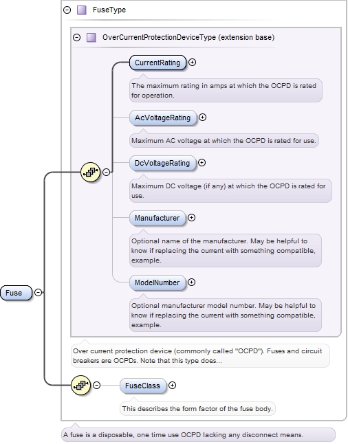
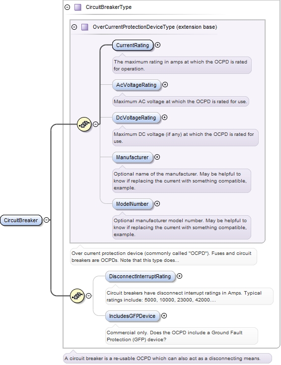
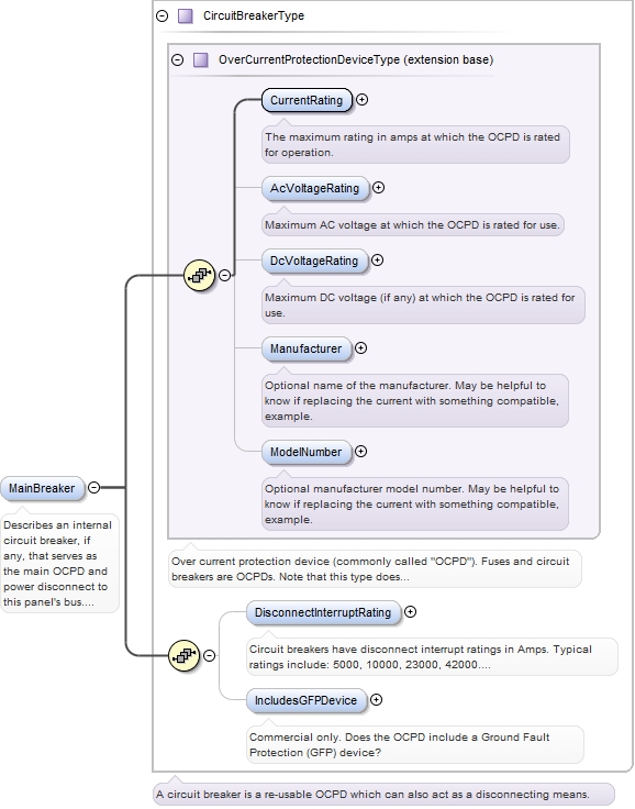
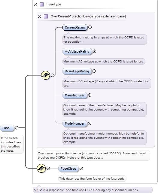
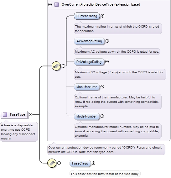
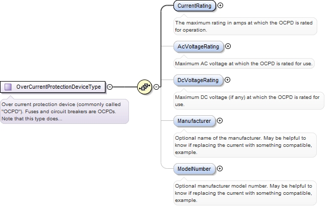
The maximum rating in amps at which the OCPD is rated for operation.
Diagram
Type
xs:integer
Properties
content:
simple
minOccurs:
1
maxOccurs:
1
Source
<xs:element name="CurrentRating" type="xs:integer" minOccurs="1" maxOccurs="1"><xs:annotation><xs:documentation>The maximum rating in amps at which the OCPD is rated for operation.</xs:documentation></xs:annotation></xs:element>
Maximum AC voltage at which the OCPD is rated for use.
Diagram
Type
xs:integer
Properties
content:
simple
minOccurs:
0
Source
<xs:element name="AcVoltageRating" type="xs:integer" minOccurs="0"><xs:annotation><xs:documentation>Maximum AC voltage at which the OCPD is rated for use.</xs:documentation></xs:annotation></xs:element>
Maximum DC voltage (if any) at which the OCPD is rated for use.
Diagram
Type
xs:integer
Properties
content:
simple
minOccurs:
0
Source
<xs:element minOccurs="0" name="DcVoltageRating" type="xs:integer"><xs:annotation><xs:documentation>Maximum DC voltage (if any) at which the OCPD is rated for use.</xs:documentation></xs:annotation></xs:element>
Optional name of the manufacturer. May be helpful to know if replacing the current with something compatible, example.
Diagram
Type
xs:string
Properties
content:
simple
minOccurs:
0
Source
<xs:element minOccurs="0" name="Manufacturer" type="xs:string"><xs:annotation><xs:documentation>Optional name of the manufacturer. May be helpful to know if replacing the current with something compatible, example.</xs:documentation></xs:annotation></xs:element>
Optional manufacturer model number. May be helpful to know if replacing the current with something compatible, example.
Diagram
Type
xs:string
Properties
content:
simple
minOccurs:
0
Source
<xs:element minOccurs="0" name="ModelNumber" type="xs:string"><xs:annotation><xs:documentation>Optional manufacturer model number. May be helpful to know if replacing the current with something compatible, example.</xs:documentation></xs:annotation></xs:element>
<xs:element minOccurs="0" name="FuseClass" type="xs:string"><xs:annotation><xs:documentation>This describes the form factor of the fuse body.</xs:documentation></xs:annotation></xs:element>
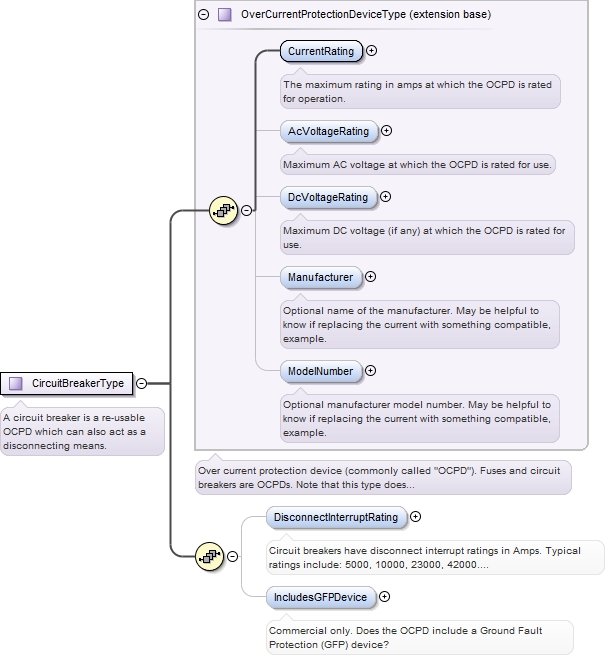
Circuit breakers have disconnect interrupt ratings in Amps. Typical ratings include: 5000, 10000, 23000, 42000. Typically if rating is not listed on a breaker, it is 5000.
Diagram
Type
xs:integer
Properties
content:
simple
minOccurs:
0
maxOccurs:
1
Source
<xs:element minOccurs="0" name="DisconnectInterruptRating" type="xs:integer" maxOccurs="1"><xs:annotation><xs:documentation>Circuit breakers have disconnect interrupt ratings in Amps. Typical ratings include: 5000, 10000, 23000, 42000. Typically if rating is not listed on a breaker, it is 5000.</xs:documentation></xs:annotation></xs:element>
Commercial only. Does the OCPD include a Ground Fault Protection (GFP) device?
Diagram
Type
xs:boolean
Properties
content:
simple
minOccurs:
0
maxOccurs:
1
Source
<xs:element minOccurs="0" name="IncludesGFPDevice" type="xs:boolean" maxOccurs="1"><xs:annotation><xs:documentation>Commercial only. Does the OCPD include a Ground Fault Protection (GFP) device?</xs:documentation></xs:annotation></xs:element>
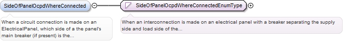
When a circuit connection is made on an ElectricalPanel, which side of a the panel's main breaker (if present) is the interconnection made (supply or load side)?This is a very important consideration, as the NEC dictates the maximum allowable interconnected current, and it is very different for each side of the OCPD. For example, when tied to the load side of a panel's bus, the total of all circuits amperage can sum to 120% of the bus's current rating when using a backfed breaker. If tied to the supply side, the allowable PV circuit amperage can go up to the maximum rated amperage of the bus (as the main breaker protects the load side). Note that this also differs between residential and commercial systems. Most residential systems are interconnected on the load side. Conversely, most commercial systems are interconnected on the supply side because NEC 690 currently has no 120% rule on commercial load side tie-in (significantly limiting possible size), and also commercial system equipment is more likely to have connections available on the supply side (e.g. lugs).
<xs:element default="load-side" minOccurs="0" name="SideOfPanelOcpdWhereConnected" type="SideOfPanelOcpdWhereConnectedEnumType"><xs:annotation><xs:documentation>When a circuit connection is made on an ElectricalPanel, which side of a the panel's main breaker (if present) is the interconnection made (supply or load side)? This is a very important consideration, as the NEC dictates the maximum allowable interconnected current, and it is very different for each side of the OCPD. For example, when tied to the load side of a panel's bus, the total of all circuits amperage can sum to 120% of the bus's current rating when using a backfed breaker. If tied to the supply side, the allowable PV circuit amperage can go up to the maximum rated amperage of the bus (as the main breaker protects the load side). Note that this also differs between residential and commercial systems. Most residential systems are interconnected on the load side. Conversely, most commercial systems are interconnected on the supply side because NEC 690 currently has no 120% rule on commercial load side tie-in (significantly limiting possible size), and also commercial system equipment is more likely to have connections available on the supply side (e.g. lugs).</xs:documentation></xs:annotation></xs:element>
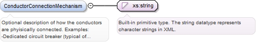
Optional description of how the conductors are phyisically connected. Examples:-Dedicated circuit breaker (typical of load side, but breaker-can also be on service side if hot-bussed panel has breaker slot on the service side)-lugs (supply side typical)-wire taps (supply side typical)
Diagram
Type
xs:string
Properties
content:
simple
minOccurs:
0
Source
<xs:element minOccurs="0" name="ConductorConnectionMechanism" type="xs:string"><xs:annotation><xs:documentation>Optional description of how the conductors are phyisically connected. Examples: -Dedicated circuit breaker (typical of load side, but breaker-can also be on service side if hot-bussed panel has breaker slot on the service side) -lugs (supply side typical) -wire taps (supply side typical)</xs:documentation></xs:annotation></xs:element>
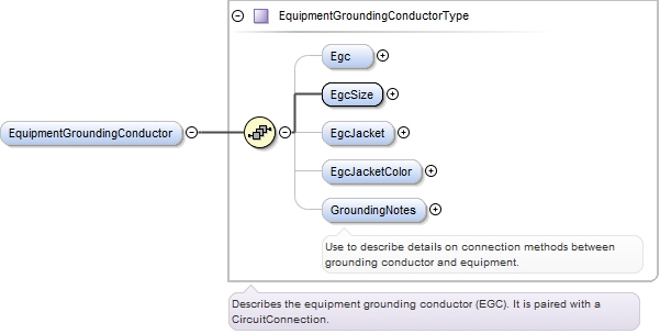
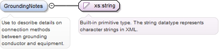
Use to describe details on connection methods between grounding conductor and equipment.
Diagram
Type
xs:string
Properties
content:
simple
minOccurs:
0
Source
<xs:element minOccurs="0" name="GroundingNotes" type="xs:string"><xs:annotation><xs:documentation>Use to describe details on connection methods between grounding conductor and equipment.</xs:documentation></xs:annotation></xs:element>
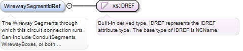
The Wireway Segments through which this circuit connection runs. Can include ConduitSegments, WirewayBoxes, or both. Note that the CircuitConnection can be routed through a DisconnectSwitch or StandAloneMeterSocket without actually being switched or metered. If the CircuitConnection is disconnected or metered, it should be called out in a separate Disconnect or StandAloneMeter element within the CircuitConnection.
Diagram
Type
xs:IDREF
Properties
content:
simple
minOccurs:
0
maxOccurs:
unbounded
Source
<xs:element name="WirewaySegmentIdRef" type="xs:IDREF" minOccurs="0" maxOccurs="unbounded"><xs:annotation><xs:documentation>The Wireway Segments through which this circuit connection runs. Can include ConduitSegments, WirewayBoxes, or both. Note that the CircuitConnection can be routed through a DisconnectSwitch or StandAloneMeterSocket without actually being switched or metered. If the CircuitConnection is disconnected or metered, it should be called out in a separate Disconnect or StandAloneMeter element within the CircuitConnection.</xs:documentation></xs:annotation></xs:element>
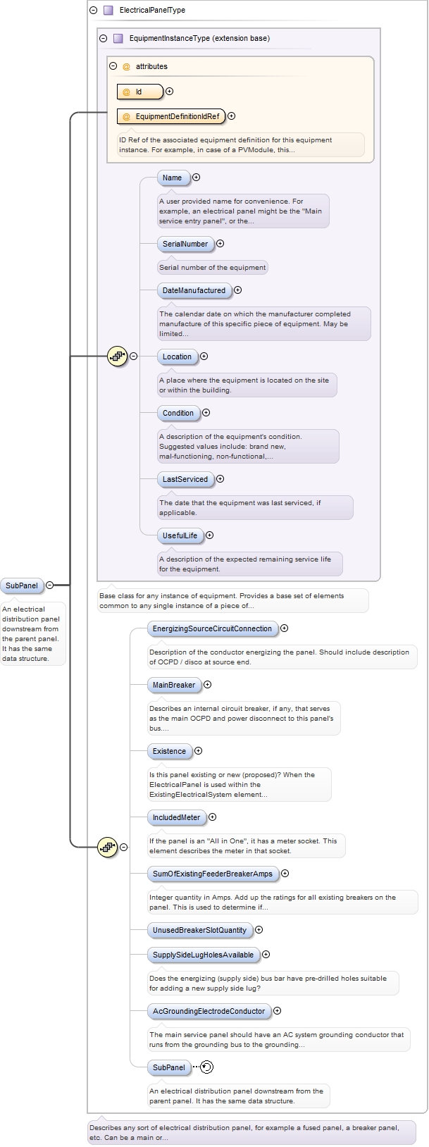
Describes an internal circuit breaker, if any, that serves as the main OCPD and power disconnect to this panel's bus. Note that the ElectricPanel may or may not have an internal main breaker. Panels with or without a main internal breaker may also have an OCPD on the ElectricPanel's CircuitConnection element which serves as the energizing source for this panel.
<xs:element minOccurs="0" name="MainBreaker" type="CircuitBreakerType" maxOccurs="1"><xs:annotation><xs:documentation>Describes an internal circuit breaker, if any, that serves as the main OCPD and power disconnect to this panel's bus. Note that the ElectricPanel may or may not have an internal main breaker. Panels with or without a main internal breaker may also have an OCPD on the ElectricPanel's CircuitConnection element which serves as the energizing source for this panel.</xs:documentation></xs:annotation></xs:element>
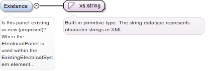
Is this panel existing or new (proposed)? When the ElectricalPanel is used within the ExistingElectricalSystem element inside of a Project's Site element, this is assumed to be an existing panel. However, if the panel is just being defined within a PvDesign's AcTie-InPanel element, then its important to know if the panel being described already exists or is new (and therefore part of the scope of work).
Diagram
Type
xs:string
Properties
content:
simple
minOccurs:
0
Source
<xs:element minOccurs="0" name="Existence" type="xs:string"><xs:annotation><xs:documentation>Is this panel existing or new (proposed)? When the ElectricalPanel is used within the ExistingElectricalSystem element inside of a Project's Site element, this is assumed to be an existing panel. However, if the panel is just being defined within a PvDesign's AcTie-InPanel element, then its important to know if the panel being described already exists or is new (and therefore part of the scope of work).</xs:documentation></xs:annotation></xs:element>
ID Ref of the associated equipment definition for this equipment instance. For example, in case of a PVModule, this would be the ID of the PvModuleDefinition element that describes this particular PV module instance.
<xs:element minOccurs="0" name="IncludedMeter" type="EquipmentInstanceType"><xs:annotation><xs:documentation>If the panel is an "All in One", it has a meter socket. This element describes the meter in that socket.</xs:documentation></xs:annotation></xs:element>
Integer quantity in Amps. Add up the ratings for all existing breakers on the panel. This is used to determine if existing panel configuration meets code, and if additional breakers can be added.
Diagram
Type
xs:integer
Properties
content:
simple
minOccurs:
0
maxOccurs:
1
Source
<xs:element maxOccurs="1" minOccurs="0" name="SumOfExistingFeederBreakerAmps" type="xs:integer"><xs:annotation><xs:documentation>Integer quantity in Amps. Add up the ratings for all existing breakers on the panel. This is used to determine if existing panel configuration meets code, and if additional breakers can be added.</xs:documentation></xs:annotation></xs:element>
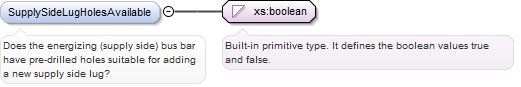
Does the energizing (supply side) bus bar have pre-drilled holes suitable for adding a new supply side lug?
Diagram
Type
xs:boolean
Properties
content:
simple
minOccurs:
0
Source
<xs:element minOccurs="0" name="SupplySideLugHolesAvailable" type="xs:boolean"><xs:annotation><xs:documentation>Does the energizing (supply side) bus bar have pre-drilled holes suitable for adding a new supply side lug?</xs:documentation></xs:annotation></xs:element>
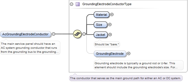
The main service panel should have an AC system grounding conductor that runs from the grounding bus to the grounding electrode. The grounding electrode is a ground rod, or U-fer, for example.
<xs:element minOccurs="0" name="AcGroundingElectrodeConductor" type="GroundingElectrodeConductorType"><xs:annotation><xs:documentation>The main service panel should have an AC system grounding conductor that runs from the grounding bus to the grounding electrode. The grounding electrode is a ground rod, or U-fer, for example.</xs:documentation></xs:annotation></xs:element>
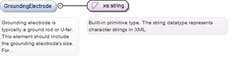
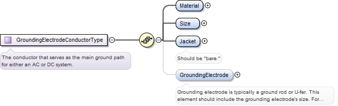
Grounding electrode is typically a ground rod or U-fer. This element should include the grounding electrode's size. For example "3/4 in ground rod."
Diagram
Type
xs:string
Properties
content:
simple
minOccurs:
0
Source
<xs:element minOccurs="0" name="GroundingElectrode" type="xs:string"><xs:annotation><xs:documentation>Grounding electrode is typically a ground rod or U-fer. This element should include the grounding electrode's size. For example "3/4 in ground rod."</xs:documentation></xs:annotation></xs:element>
ID Ref of the associated equipment definition for this equipment instance. For example, in case of a PVModule, this would be the ID of the PvModuleDefinition element that describes this particular PV module instance.
<xs:element minOccurs="0" name="SubPanel" type="ElectricalPanelType"><xs:annotation><xs:documentation>An electrical distribution panel downstream from the parent panel. It has the same data structure.</xs:documentation></xs:annotation></xs:element>
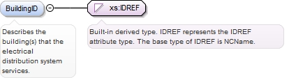
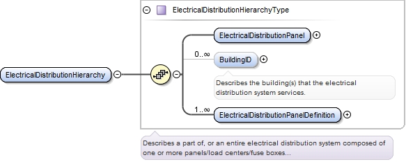
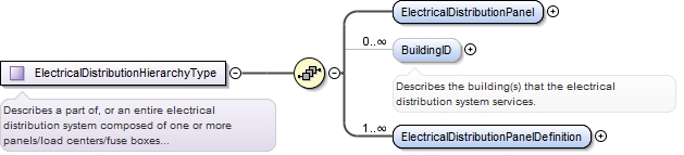
Describes the building(s) that the electrical distribution system services.
Diagram
Type
xs:IDREF
Properties
content:
simple
minOccurs:
0
maxOccurs:
unbounded
Source
<xs:element maxOccurs="unbounded" minOccurs="0" name="BuildingID" type="xs:IDREF"><xs:annotation><xs:documentation>Describes the building(s) that the electrical distribution system services.</xs:documentation></xs:annotation></xs:element>
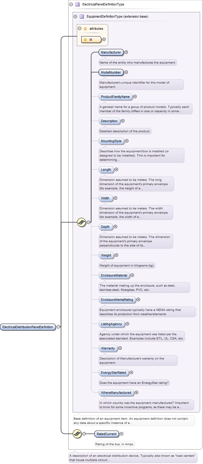
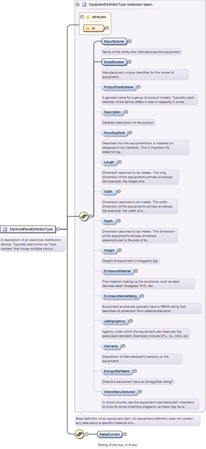
<xs:element name="RatedCurrent" type="xs:integer" minOccurs="1" maxOccurs="1"><xs:annotation><xs:documentation>Rating of the bus, in Amps.</xs:documentation></xs:annotation></xs:element>
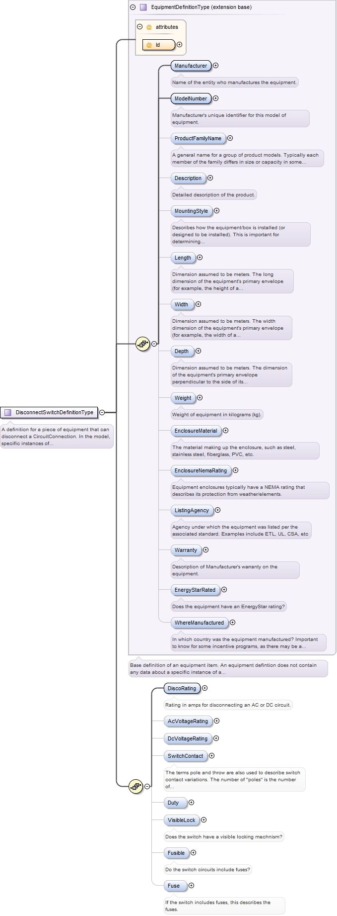
Rating in amps for disconnecting an AC or DC circuit.
Diagram
Type
xs:integer
Properties
content:
simple
minOccurs:
1
Source
<xs:element minOccurs="1" name="DiscoRating" type="xs:integer"><xs:annotation><xs:documentation>Rating in amps for disconnecting an AC or DC circuit.</xs:documentation></xs:annotation></xs:element>
The terms pole and throw are also used to describe switch contact variations. The number of "poles" is the number of separate circuits which are controlled by a switch. For example, a "2-pole" switch has two separate identical sets of contacts controlled by the same knob. The number of "throws" is the number of separate positions that the switch can adopt. A single-throw switch has one pair of contacts that can either be closed or open. A double-throw switch has a contact that can be connected to either of two other contacts, a triple-throw has a contact which can be connected to one of three other contacts, etc
<xs:element name="SwitchContact" minOccurs="0" type="SwitchContactActionEnumType"><xs:annotation><xs:documentation>The terms pole and throw are also used to describe switch contact variations. The number of "poles" is the number of separate circuits which are controlled by a switch. For example, a "2-pole" switch has two separate identical sets of contacts controlled by the same knob. The number of "throws" is the number of separate positions that the switch can adopt. A single-throw switch has one pair of contacts that can either be closed or open. A double-throw switch has a contact that can be connected to either of two other contacts, a triple-throw has a contact which can be connected to one of three other contacts, etc</xs:documentation></xs:annotation></xs:element>
<xs:element minOccurs="0" name="VisibleLock" type="xs:boolean"><xs:annotation><xs:documentation>Does the switch have a visible locking mechnism?</xs:documentation></xs:annotation></xs:element>
<xs:element minOccurs="0" name="Fusible" type="xs:boolean"><xs:annotation><xs:documentation>Do the switch circuits include fuses?</xs:documentation></xs:annotation></xs:element>
<xs:element minOccurs="0" name="Fuse" type="FuseType"><xs:annotation><xs:documentation>If the switch includes fuses, this describes the fuses.</xs:documentation></xs:annotation></xs:element>
The length in feet of the conduit segment. Values should be rounded up to nearest foot.
Diagram
Type
xs:double
Properties
content:
simple
minOccurs:
0
Source
<xs:element name="ConduitLength" type="xs:double" minOccurs="0"><xs:annotation><xs:documentation>The length in feet of the conduit segment. Values should be rounded up to nearest foot.</xs:documentation></xs:annotation></xs:element>
The ID Ref for another WirewaySegment or Equipment to which the Coduit segment connects. Conduit is a pipe with 2 ends, so it has a maximum of two WirewaySegments or Equipment to which it connects. Boxes can have many WirewaySegment connections.
Diagram
Type
xs:IDREF
Properties
content:
simple
minOccurs:
0
maxOccurs:
2
Source
<xs:element maxOccurs="2" name="SegmentConnection" type="xs:IDREF" minOccurs="0"><xs:annotation><xs:documentation>The ID Ref for another WirewaySegment or Equipment to which the Coduit segment connects. Conduit is a pipe with 2 ends, so it has a maximum of two WirewaySegments or Equipment to which it connects. Boxes can have many WirewaySegment connections.</xs:documentation></xs:annotation></xs:element>
In cases where the CircuitConnection element is used within an EquipmentInstance that does not have a parent element to which the CircuitConnection is assumed to connect, a reference ID can be used to associate this CircuitConnection to another EquipmentInstance elsewhere in a document instance. For example, a PvSystem may have an AcPointOfConnection that uses a new ElectricalPanel as an AC combiner for more than one Inverter. The new electrical panel can be described by an ElectricalPanel element in the PvDesign (which in turn refers to an ElectricalPanelDefinition element).in the AcPointOfConnection's EquipmentWhereConnected element. That ElectricPanel's EnergizingCircuitConnection element may reference another ElectricPanel in an instance of the Project's ExistingElectricalHierarchy element.
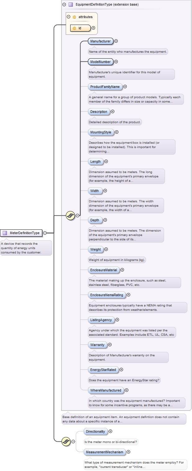
<xs:element minOccurs="0" name="Directionality" type="xs:string"><xs:annotation><xs:documentation>Is the meter mono or bi-directional?</xs:documentation></xs:annotation></xs:element>
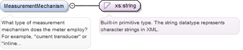
What type of measurement mechanism does the meter employ? For example, "current transducer" or "inline electro-mechanical"
Diagram
Type
xs:string
Properties
content:
simple
minOccurs:
0
Source
<xs:element minOccurs="0" name="MeasurementMechanism" type="xs:string"><xs:annotation><xs:documentation>What type of measurement mechanism does the meter employ? For example, "current transducer" or "inline electro-mechanical"</xs:documentation></xs:annotation></xs:element>
Complex Type WirewaySegmentType
Namespace
http://www.iepmodel.net
Annotations
Base definition of a WirewaySegment, which is a distinct piece of wireway through which electrical wiring is housed for its prtotection and the protection of people and property. Wireway segments can be either electrical conduit or boxes. Multiple segments are connected to form a single continuous path for one or more CircuitConnections. Each segment is distinct by its characteristics.
If the WirewaySegment is a junction box or disconnect switch, this refers to its EquipmentDefinition. A WirewayBox may be a pass through where multiple ConduitSegments are combined into a single ConduitSegment for example. A disconnect switch box may also be modeled as a WirewayBox, provided that the circuit(s) involved are simply disoconnected and not combined in any way. DO NOT use WirewayBox to represent a combiner, or distribution panel.
<xs:complexType name="WirewaySegmentType" abstract="true"><xs:annotation><xs:documentation>Base definition of a WirewaySegment, which is a distinct piece of wireway through which electrical wiring is housed for its prtotection and the protection of people and property. Wireway segments can be either electrical conduit or boxes. Multiple segments are connected to form a single continuous path for one or more CircuitConnections. Each segment is distinct by its characteristics.</xs:documentation></xs:annotation><xs:sequence><xs:element name="Name" type="xs:string" minOccurs="0"><xs:annotation><xs:documentation>A name given in context to the system.</xs:documentation></xs:annotation></xs:element><xs:element minOccurs="0" name="LocationDescription" type="xs:string"><xs:annotation><xs:documentation>Description of where the segment is, or through which locations it traverses. Include descriptions such as attic, interior, exterior, roof, or trench.</xs:documentation></xs:annotation></xs:element><xs:element name="HighTempExposure" type="xs:boolean" minOccurs="0" maxOccurs="1"><xs:annotation><xs:documentation>Is the conduit exposed to high temperatures? For example, sitting on a roof in direct sun. If so, any conductors contained within the segment may have to have their rated current carrying capacity derated.</xs:documentation></xs:annotation></xs:element></xs:sequence><xs:attribute name="Id" type="xs:ID" use="required"/><xs:attribute name="EquipmentDefinitionIdRef" type="xs:IDREF"><xs:annotation><xs:documentation>If the WirewaySegment is a junction box or disconnect switch, this refers to its EquipmentDefinition. A WirewayBox may be a pass through where multiple ConduitSegments are combined into a single ConduitSegment for example. A disconnect switch box may also be modeled as a WirewayBox, provided that the circuit(s) involved are simply disoconnected and not combined in any way. DO NOT use WirewayBox to represent a combiner, or distribution panel.</xs:documentation></xs:annotation></xs:attribute></xs:complexType>
Complex Type ElectricalDistributionHierarchyType
Namespace
http://www.iepmodel.net
Annotations
Describes a part of, or an entire electrical distribution system composed of one or more panels/load centers/fuse boxes in a hierarchical tree arrangement.
<xs:complexType name="ElectricalDistributionHierarchyType"><xs:annotation><xs:documentation>Describes a part of, or an entire electrical distribution system composed of one or more panels/load centers/fuse boxes in a hierarchical tree arrangement.</xs:documentation></xs:annotation><xs:sequence><xs:element name="ElectricalDistributionPanel" type="ElectricalPanelType"/><xs:element maxOccurs="unbounded" minOccurs="0" name="BuildingID" type="xs:IDREF"><xs:annotation><xs:documentation>Describes the building(s) that the electrical distribution system services.</xs:documentation></xs:annotation></xs:element><xs:element maxOccurs="unbounded" name="ElectricalDistributionPanelDefinition" type="ElectricalPanelDefinitionType"/></xs:sequence></xs:complexType>
Complex Type ElectricalPanelType
Namespace
http://www.iepmodel.net
Annotations
Describes any sort of electrical distribution panel, for example a fused panel, a breaker panel, etc. Can be a main or sub-panel.
ID Ref of the associated equipment definition for this equipment instance. For example, in case of a PVModule, this would be the ID of the PvModuleDefinition element that describes this particular PV module instance.
<xs:complexType name="ElectricalPanelType"><xs:annotation><xs:documentation>Describes any sort of electrical distribution panel, for example a fused panel, a breaker panel, etc. Can be a main or sub-panel.</xs:documentation></xs:annotation><xs:complexContent><xs:extension base="EquipmentInstanceType"><xs:sequence><xs:element minOccurs="0" name="EnergizingSourceCircuitConnection" type="CircuitConnectionType" maxOccurs="1"><xs:annotation><xs:documentation>Description of the conductor energizing the panel. Should include description of OCPD / disco at source end.</xs:documentation></xs:annotation></xs:element><xs:element minOccurs="0" name="MainBreaker" type="CircuitBreakerType" maxOccurs="1"><xs:annotation><xs:documentation>Describes an internal circuit breaker, if any, that serves as the main OCPD and power disconnect to this panel's bus. Note that the ElectricPanel may or may not have an internal main breaker. Panels with or without a main internal breaker may also have an OCPD on the ElectricPanel's CircuitConnection element which serves as the energizing source for this panel.</xs:documentation></xs:annotation></xs:element><xs:element minOccurs="0" name="Existence" type="xs:string"><xs:annotation><xs:documentation>Is this panel existing or new (proposed)? When the ElectricalPanel is used within the ExistingElectricalSystem element inside of a Project's Site element, this is assumed to be an existing panel. However, if the panel is just being defined within a PvDesign's AcTie-InPanel element, then its important to know if the panel being described already exists or is new (and therefore part of the scope of work).</xs:documentation></xs:annotation></xs:element><xs:element minOccurs="0" name="IncludedMeter" type="EquipmentInstanceType"><xs:annotation><xs:documentation>If the panel is an "All in One", it has a meter socket. This element describes the meter in that socket.</xs:documentation></xs:annotation></xs:element><xs:element maxOccurs="1" minOccurs="0" name="SumOfExistingFeederBreakerAmps" type="xs:integer"><xs:annotation><xs:documentation>Integer quantity in Amps. Add up the ratings for all existing breakers on the panel. This is used to determine if existing panel configuration meets code, and if additional breakers can be added.</xs:documentation></xs:annotation></xs:element><xs:element minOccurs="0" name="UnusedBreakerSlotQuantity" type="xs:integer" maxOccurs="1"/><xs:element minOccurs="0" name="SupplySideLugHolesAvailable" type="xs:boolean"><xs:annotation><xs:documentation>Does the energizing (supply side) bus bar have pre-drilled holes suitable for adding a new supply side lug?</xs:documentation></xs:annotation></xs:element><xs:element minOccurs="0" name="AcGroundingElectrodeConductor" type="GroundingElectrodeConductorType"><xs:annotation><xs:documentation>The main service panel should have an AC system grounding conductor that runs from the grounding bus to the grounding electrode. The grounding electrode is a ground rod, or U-fer, for example.</xs:documentation></xs:annotation></xs:element><xs:element minOccurs="0" name="SubPanel" type="ElectricalPanelType"><xs:annotation><xs:documentation>An electrical distribution panel downstream from the parent panel. It has the same data structure.</xs:documentation></xs:annotation></xs:element></xs:sequence></xs:extension></xs:complexContent></xs:complexType>
Complex Type CircuitConnectionType
Namespace
http://www.iepmodel.net
Annotations
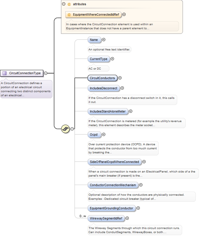
A CircuitConnection defines a portion of an electrical circuit connecting two distinct components of an electrical system (for example, the connection of a PV String to a CombinerBox). A CircuitConnection is made by conductors. One end of the CircuitConnection is the element in which the CircuitConnection exists, and the other end is typically the parent element of the element in which the CircuitConnection element resides. For example, a CombinerBox element can have multiple PvString elements within it. Each PvString element contains a CircuitConnection element which defines its connection to the CombinerBox. A CombinerBox has a CircuitConnection element which defines its connection to an InverterDcInput, for example.Optionally, the CircuitConnectionType contains an optional EquipmentWhereConnectedIdRef attribute which can be used to reference another electrical equipment element in another part of a document. For example, a PvDesign's Inverter has no parent element. Instead, it's AcTie-InCircuitConnection uses the EquipmentWhereConnectedIdRef attribute to reference either an ElectricalPanel within the PvDesign, or an ElectricalPanel within a Project's ExistingElectricalDistributionHierarchy element may exist.
In cases where the CircuitConnection element is used within an EquipmentInstance that does not have a parent element to which the CircuitConnection is assumed to connect, a reference ID can be used to associate this CircuitConnection to another EquipmentInstance elsewhere in a document instance. For example, a PvSystem may have an AcPointOfConnection that uses a new ElectricalPanel as an AC combiner for more than one Inverter. The new electrical panel can be described by an ElectricalPanel element in the PvDesign (which in turn refers to an ElectricalPanelDefinition element).in the AcPointOfConnection's EquipmentWhereConnected element. That ElectricPanel's EnergizingCircuitConnection element may reference another ElectricPanel in an instance of the Project's ExistingElectricalHierarchy element.
Source
<xs:complexType name="CircuitConnectionType"><xs:annotation><xs:documentation>A CircuitConnection defines a portion of an electrical circuit connecting two distinct components of an electrical system (for example, the connection of a PV String to a CombinerBox). A CircuitConnection is made by conductors. One end of the CircuitConnection is the element in which the CircuitConnection exists, and the other end is typically the parent element of the element in which the CircuitConnection element resides. For example, a CombinerBox element can have multiple PvString elements within it. Each PvString element contains a CircuitConnection element which defines its connection to the CombinerBox. A CombinerBox has a CircuitConnection element which defines its connection to an InverterDcInput, for example. Optionally, the CircuitConnectionType contains an optional EquipmentWhereConnectedIdRef attribute which can be used to reference another electrical equipment element in another part of a document. For example, a PvDesign's Inverter has no parent element. Instead, it's AcTie-InCircuitConnection uses the EquipmentWhereConnectedIdRef attribute to reference either an ElectricalPanel within the PvDesign, or an ElectricalPanel within a Project's ExistingElectricalDistributionHierarchy element may exist.</xs:documentation></xs:annotation><xs:sequence><xs:element minOccurs="0" name="Name" type="xs:string"><xs:annotation><xs:documentation>An optional free text identifier.</xs:documentation></xs:annotation></xs:element><xs:element name="CurrentType" minOccurs="0" type="CurrentEnumType"><xs:annotation><xs:documentation>AC or DC</xs:documentation></xs:annotation></xs:element><xs:element name="CircuitConductors" type="CircuitConnectionConductorType"/><xs:element minOccurs="0" name="IncludesDisconnect"><xs:annotation><xs:documentation>If the CircuitConnection has a disconnect switch in it, this calls it out.</xs:documentation></xs:annotation><xs:complexType><xs:attribute name="WirewayBoxIdRef" type="xs:IDREF" use="required"><xs:annotation><xs:documentation>Reference to an instance of the DisconnectSwitch modeled generally as a WirewayBox. A disconnect switch can switch more than one CircuitConnection, so it is defined external to the CircuitConnection.</xs:documentation></xs:annotation></xs:attribute><xs:attribute name="ConductorSegmentIdRef" type="xs:IDREF" use="required"><xs:annotation><xs:documentation>ConductorSegment that contains the disconnect switch.</xs:documentation></xs:annotation></xs:attribute></xs:complexType></xs:element><xs:element minOccurs="0" name="IncludesStandAloneMeter"><xs:annotation><xs:documentation>If the CircuitConnection is metered (for example the utility's revenue meter), this element describes the meter socket and meter. The meter and socket are individual entities. The MeterSocket is modeled as a simple WirewayBox.</xs:documentation></xs:annotation><xs:complexType><xs:sequence><xs:element name="MeterSocket" type="WirewayBoxType"/><xs:element name="Meter" type="EquipmentInstanceType"/></xs:sequence><xs:attribute name="ConductorSegmentIdRef" type="xs:IDREF"/></xs:complexType></xs:element><xs:element name="Ocpd" minOccurs="0" form="unqualified"><xs:annotation><xs:documentation>Over current protection device (OCPD). A device that protects the conductor from too much current by breaking the circuit. Fuses and circuit breakers are OCPDs. In this schema, an OCPD is not a piece of equipment, but rather a component within a piece of equipment. It is not necessary to include a mfr and model in most cases, but knowing the type and rating is required.</xs:documentation></xs:annotation><xs:complexType><xs:choice><xs:element name="Fuse" type="FuseType"/><xs:element name="CircuitBreaker" type="CircuitBreakerType"/></xs:choice><xs:attribute name="EquipmentWhereLocatedIdRef"><xs:annotation><xs:documentation>The ID referring to the equipment in which the OCPD is installed. In most cases, it is the parent Equipment of the CircuitConnection's immediate parent element. For example, if the CircuitConnection is within a StringInverter element, then the circuit breaker within the ElectricalPanel to which the Inverter connects will most like be the referenced OCPD.</xs:documentation></xs:annotation></xs:attribute></xs:complexType></xs:element><xs:element default="load-side" minOccurs="0" name="SideOfPanelOcpdWhereConnected" type="SideOfPanelOcpdWhereConnectedEnumType"><xs:annotation><xs:documentation>When a circuit connection is made on an ElectricalPanel, which side of a the panel's main breaker (if present) is the interconnection made (supply or load side)? This is a very important consideration, as the NEC dictates the maximum allowable interconnected current, and it is very different for each side of the OCPD. For example, when tied to the load side of a panel's bus, the total of all circuits amperage can sum to 120% of the bus's current rating when using a backfed breaker. If tied to the supply side, the allowable PV circuit amperage can go up to the maximum rated amperage of the bus (as the main breaker protects the load side). Note that this also differs between residential and commercial systems. Most residential systems are interconnected on the load side. Conversely, most commercial systems are interconnected on the supply side because NEC 690 currently has no 120% rule on commercial load side tie-in (significantly limiting possible size), and also commercial system equipment is more likely to have connections available on the supply side (e.g. lugs).</xs:documentation></xs:annotation></xs:element><xs:element minOccurs="0" name="ConductorConnectionMechanism" type="xs:string"><xs:annotation><xs:documentation>Optional description of how the conductors are phyisically connected. Examples: -Dedicated circuit breaker (typical of load side, but breaker-can also be on service side if hot-bussed panel has breaker slot on the service side) -lugs (supply side typical) -wire taps (supply side typical)</xs:documentation></xs:annotation></xs:element><xs:element minOccurs="0" name="EquipmentGroundingConductor" type="EquipmentGroundingConductorType"/><xs:element name="WirewaySegmentIdRef" type="xs:IDREF" minOccurs="0" maxOccurs="unbounded"><xs:annotation><xs:documentation>The Wireway Segments through which this circuit connection runs. Can include ConduitSegments, WirewayBoxes, or both. Note that the CircuitConnection can be routed through a DisconnectSwitch or StandAloneMeterSocket without actually being switched or metered. If the CircuitConnection is disconnected or metered, it should be called out in a separate Disconnect or StandAloneMeter element within the CircuitConnection.</xs:documentation></xs:annotation></xs:element></xs:sequence><xs:attribute name="EquipmentWhereConnectedIdRef" type="xs:IDREF"><xs:annotation><xs:documentation>In cases where the CircuitConnection element is used within an EquipmentInstance that does not have a parent element to which the CircuitConnection is assumed to connect, a reference ID can be used to associate this CircuitConnection to another EquipmentInstance elsewhere in a document instance. For example, a PvSystem may have an AcPointOfConnection that uses a new ElectricalPanel as an AC combiner for more than one Inverter. The new electrical panel can be described by an ElectricalPanel element in the PvDesign (which in turn refers to an ElectricalPanelDefinition element). in the AcPointOfConnection's EquipmentWhereConnected element. That ElectricPanel's EnergizingCircuitConnection element may reference another ElectricPanel in an instance of the Project's ExistingElectricalHierarchy element.</xs:documentation></xs:annotation></xs:attribute></xs:complexType>
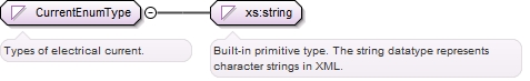
<xs:simpleType name="CurrentEnumType"><xs:annotation><xs:documentation>Types of electrical current.</xs:documentation></xs:annotation><xs:restriction base="xs:string"><xs:enumeration value="AC"/><xs:enumeration value="DC"/></xs:restriction></xs:simpleType>
Complex Type CircuitConnectionConductorType
Namespace
http://www.iepmodel.net
Annotations
A CircuitConnectionConductor can be made up of multiple segments of wire, as long as they share the same current carrying capacity, defined by its ConductorSize. In PV Systems, for example, its common for an array's wiring to transition from wire outside of conduit into wire inside conduit. The wire is spliced together within a box (e.g. WirewayBox).
<xs:complexType name="CircuitConnectionConductorType"><xs:annotation><xs:documentation>A CircuitConnectionConductor can be made up of multiple segments of wire, as long as they share the same current carrying capacity, defined by its ConductorSize. In PV Systems, for example, its common for an array's wiring to transition from wire outside of conduit into wire inside conduit. The wire is spliced together within a box (e.g. WirewayBox).</xs:documentation></xs:annotation><xs:sequence><xs:element name="ConductorSize" type="ConductorSizeEnumType"><xs:annotation><xs:documentation>Wire diameter, given in American Wire Gauge (AWG), or kcmil. The entire circuit connection conductor is assumed to be the same size conductor, even if it is physically made up of multiple conductor segments that are different kinds of wire.</xs:documentation></xs:annotation></xs:element><xs:element minOccurs="1" name="ConductorQuantity" type="xs:integer"><xs:annotation><xs:documentation>Number of conductors used to connect the circuit. Residential 120V uses 2 conductors, whereas 240V typically uses three conductors, and commercial three phase typically is 4 conductors.</xs:documentation></xs:annotation></xs:element><xs:element minOccurs="0" name="PrimaryConductorSegment" type="ConductorSegmentType"><xs:annotation><xs:documentation>This is the segment of the CircuitConductor that is connected directly to the electrical component that this CircuitConnection belongs to. For example, let's assume that this ConductorSegment is part of a CircuitConnection for a PvString. The PvString typically starts out as USE-2 wire from the PV Modules and may transition to THWN-2 wire once inside a J-box (modeled as a Wireway box in this schema). The USE-2 segment of the conductor is the Primary segment, while the THWN-2 wire is a secondary segment. All CircuitConnectionConductors have a primary segment, only some have any secondary instances. If there are more than one, then the splices made beween them are described by the ConnectsToConductorSegmentId and the WirewaySegmentWhereConnectedId attributes.</xs:documentation></xs:annotation></xs:element><xs:element maxOccurs="unbounded" minOccurs="0" name="SecondaryConductorSegment"><xs:annotation><xs:documentation>A portion of a CircuitConnectionConductor that is of a different type of wire than the Primary. All CircuitConnectionConductors have a primary segment, only some have any secondary instances. If there are more than one, then the splices made beween them are described by the ConnectsToConductorSegmentId and the WirewaySegmentWhereConnectedId attributes.</xs:documentation></xs:annotation><xs:complexType><xs:complexContent><xs:extension base="ConductorSegmentType"><xs:attribute name="ConnectsToConductorSegmentId" type="xs:IDREF" use="required"/><xs:attribute name="WirewaySegmentWhereConnectedId" type="xs:IDREF" use="required"/></xs:extension></xs:complexContent></xs:complexType></xs:element></xs:sequence></xs:complexType>
A specific portion of a circuit's wiring. This element allows for definition of multiple segments of different wire types within a single CircuitConnectionConductor.
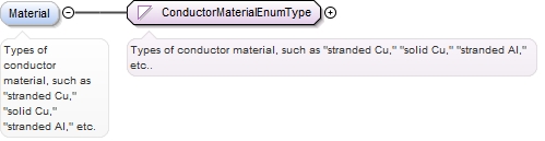
<xs:complexType name="ConductorSegmentType"><xs:annotation><xs:documentation>A specific portion of a circuit's wiring. This element allows for definition of multiple segments of different wire types within a single CircuitConnectionConductor.</xs:documentation></xs:annotation><xs:sequence><xs:element minOccurs="0" name="Material" type="ConductorMaterialEnumType"><xs:annotation><xs:documentation>Types of conductor material, such as "stranded Cu," "solid Cu," "stranded Al," etc.</xs:documentation></xs:annotation></xs:element><xs:element minOccurs="1" name="Jacket" type="ConductorJacketEnumType"><xs:annotation><xs:documentation>Type of jacketing on the conductor.</xs:documentation></xs:annotation></xs:element><xs:element minOccurs="0" name="JacketColor" type="xs:string"/><xs:element name="Length" type="xs:double" minOccurs="0" maxOccurs="1"><xs:annotation><xs:documentation>Length of this conductor connection, in feet.</xs:documentation></xs:annotation></xs:element></xs:sequence><xs:attribute name="Id" use="required" type="xs:ID"/></xs:complexType>
Simple Type ConductorMaterialEnumType
Namespace
http://www.iepmodel.net
Annotations
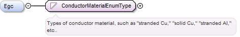
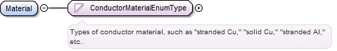
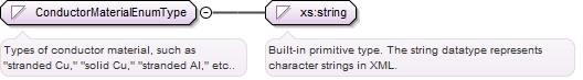
Types of conductor material, such as "stranded Cu," "solid Cu," "stranded Al," etc..
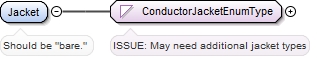
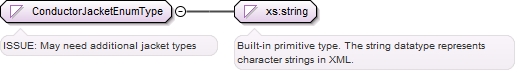
<xs:simpleType name="ConductorJacketEnumType"><xs:annotation><xs:documentation>ISSUE: May need additional jacket types</xs:documentation></xs:annotation><xs:restriction base="xs:string"><xs:enumeration value="bare"/><xs:enumeration value="USE"/><xs:enumeration value="USE-2"/><xs:enumeration value="THWN"/><xs:enumeration value="THWN-2"/><xs:enumeration value="THHN"/><xs:enumeration value="THHW"/><xs:enumeration value="XHHW-2"/><xs:enumeration value="RHW-2"/><xs:enumeration value="PV Wire"/></xs:restriction></xs:simpleType>
Complex Type WirewayBoxType
Namespace
http://www.iepmodel.net
Annotations
A WirewayBox is any electrical box through which CircuitConnections travel as a transition from one ConduitSegment to another. A WirewayBox is modeled like a piece of conduit in that they do not have their own CircuitConnections. Wireway boxes cannot change the current or voltage characteristics of any CircuitConnections passing through it. They may not combine or distribute current like a DcCombiner or ElectricalPanel. They may not change voltage characteristics such as a StringInverter. A WirewayBox may contain 1:1 wire splices or a disconnect switch (a switch does not change the current or voltage). Note that a WirewayBox may or may not refer to a defined piece of Equipment (e.g. a JunctionBoxDefintion, DisconnectSwitchDefinition, StandAloneMeterSocketDefintion). It may instead contain a free text name.
If the WirewaySegment is a junction box or disconnect switch, this refers to its EquipmentDefinition. A WirewayBox may be a pass through where multiple ConduitSegments are combined into a single ConduitSegment for example. A disconnect switch box may also be modeled as a WirewayBox, provided that the circuit(s) involved are simply disoconnected and not combined in any way. DO NOT use WirewayBox to represent a combiner, or distribution panel.
<xs:complexType name="WirewayBoxType"><xs:annotation><xs:documentation>A WirewayBox is any electrical box through which CircuitConnections travel as a transition from one ConduitSegment to another. A WirewayBox is modeled like a piece of conduit in that they do not have their own CircuitConnections. Wireway boxes cannot change the current or voltage characteristics of any CircuitConnections passing through it. They may not combine or distribute current like a DcCombiner or ElectricalPanel. They may not change voltage characteristics such as a StringInverter. A WirewayBox may contain 1:1 wire splices or a disconnect switch (a switch does not change the current or voltage). Note that a WirewayBox may or may not refer to a defined piece of Equipment (e.g. a JunctionBoxDefintion, DisconnectSwitchDefinition, StandAloneMeterSocketDefintion). It may instead contain a free text name.</xs:documentation></xs:annotation><xs:complexContent><xs:extension base="WirewaySegmentType"><xs:sequence><xs:element maxOccurs="unbounded" name="SegmentConnection" type="xs:IDREF" minOccurs="1"><xs:annotation><xs:documentation>The ID Ref for another WirewaySegment. Boxes can have many WirewaySegment connections (e.g. multiple conduit segments can terminate at a box). Conduit is a pipe with 2 ends, so it has a maximum of two WirewaySegments to which it connects.</xs:documentation></xs:annotation></xs:element></xs:sequence></xs:extension></xs:complexContent></xs:complexType>
Complex Type FuseType
Namespace
http://www.iepmodel.net
Annotations
A fuse is a disposable, one time use OCPD lacking any disconnect means.
<xs:complexType name="FuseType"><xs:annotation><xs:documentation>A fuse is a disposable, one time use OCPD lacking any disconnect means.</xs:documentation></xs:annotation><xs:complexContent><xs:extension base="OverCurrentProtectionDeviceType"><xs:sequence><xs:element minOccurs="0" name="FuseClass" type="xs:string"><xs:annotation><xs:documentation>This describes the form factor of the fuse body.</xs:documentation></xs:annotation></xs:element></xs:sequence></xs:extension></xs:complexContent></xs:complexType>
Complex Type OverCurrentProtectionDeviceType
Namespace
http://www.iepmodel.net
Annotations
Over current protection device (commonly called "OCPD"). Fuses and circuit breakers are OCPDs.
Note that this type does not extend EquipmentDefinition nor EquipmentInstance.  It is not a piece of equipment, but rather a component within a piece of equipment.  It is not necessary to include a mfr and model in most cases; knowing the type and rating is required.
<xs:complexType name="OverCurrentProtectionDeviceType" abstract="true"><xs:annotation><xs:documentation>Over current protection device (commonly called "OCPD"). Fuses and circuit breakers are OCPDs. Note that this type does not extend EquipmentDefinition nor EquipmentInstance. It is not a piece of equipment, but rather a component within a piece of equipment. It is not necessary to include a mfr and model in most cases; knowing the type and rating is required.</xs:documentation></xs:annotation><xs:sequence><xs:element name="CurrentRating" type="xs:integer" minOccurs="1" maxOccurs="1"><xs:annotation><xs:documentation>The maximum rating in amps at which the OCPD is rated for operation.</xs:documentation></xs:annotation></xs:element><xs:element name="AcVoltageRating" type="xs:integer" minOccurs="0"><xs:annotation><xs:documentation>Maximum AC voltage at which the OCPD is rated for use.</xs:documentation></xs:annotation></xs:element><xs:element minOccurs="0" name="DcVoltageRating" type="xs:integer"><xs:annotation><xs:documentation>Maximum DC voltage (if any) at which the OCPD is rated for use.</xs:documentation></xs:annotation></xs:element><xs:element minOccurs="0" name="Manufacturer" type="xs:string"><xs:annotation><xs:documentation>Optional name of the manufacturer. May be helpful to know if replacing the current with something compatible, example.</xs:documentation></xs:annotation></xs:element><xs:element minOccurs="0" name="ModelNumber" type="xs:string"><xs:annotation><xs:documentation>Optional manufacturer model number. May be helpful to know if replacing the current with something compatible, example.</xs:documentation></xs:annotation></xs:element></xs:sequence></xs:complexType>
Complex Type CircuitBreakerType
Namespace
http://www.iepmodel.net
Annotations
A circuit breaker is a re-usable OCPD which can also act as a disconnecting means.
<xs:complexType name="CircuitBreakerType"><xs:annotation><xs:documentation>A circuit breaker is a re-usable OCPD which can also act as a disconnecting means.</xs:documentation></xs:annotation><xs:complexContent><xs:extension base="OverCurrentProtectionDeviceType"><xs:sequence><xs:element minOccurs="0" name="DisconnectInterruptRating" type="xs:integer" maxOccurs="1"><xs:annotation><xs:documentation>Circuit breakers have disconnect interrupt ratings in Amps. Typical ratings include: 5000, 10000, 23000, 42000. Typically if rating is not listed on a breaker, it is 5000.</xs:documentation></xs:annotation></xs:element><xs:element minOccurs="0" name="IncludesGFPDevice" type="xs:boolean" maxOccurs="1"><xs:annotation><xs:documentation>Commercial only. Does the OCPD include a Ground Fault Protection (GFP) device?</xs:documentation></xs:annotation></xs:element></xs:sequence></xs:extension></xs:complexContent></xs:complexType>
Simple Type SideOfPanelOcpdWhereConnectedEnumType
Namespace
http://www.iepmodel.net
Annotations
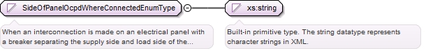
When an interconnection is made on an electrical panel with a breaker separating the supply side and load side of the panel, these list the two sides.
<xs:simpleType name="SideOfPanelOcpdWhereConnectedEnumType"><xs:annotation><xs:documentation>When an interconnection is made on an electrical panel with a breaker separating the supply side and load side of the panel, these list the two sides.</xs:documentation></xs:annotation><xs:restriction base="xs:string"><xs:enumeration value="supply-side"/><xs:enumeration value="load-side"/></xs:restriction></xs:simpleType>
Complex Type EquipmentGroundingConductorType
Namespace
http://www.iepmodel.net
Annotations
Describes the equipment grounding conductor (EGC). It is paired with a CircuitConnection.
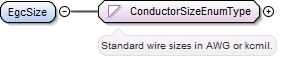
<xs:complexType name="EquipmentGroundingConductorType"><xs:annotation><xs:documentation>Describes the equipment grounding conductor (EGC). It is paired with a CircuitConnection.</xs:documentation></xs:annotation><xs:sequence><xs:element minOccurs="0" name="Egc" type="ConductorMaterialEnumType"/><xs:element name="EgcSize" type="ConductorSizeEnumType"/><xs:element minOccurs="0" name="EgcJacket" type="ConductorJacketEnumType"/><xs:element default="green" minOccurs="0" name="EgcJacketColor" type="xs:string"/><xs:element minOccurs="0" name="GroundingNotes" type="xs:string"><xs:annotation><xs:documentation>Use to describe details on connection methods between grounding conductor and equipment.</xs:documentation></xs:annotation></xs:element></xs:sequence></xs:complexType>
Complex Type GroundingElectrodeConductorType
Namespace
http://www.iepmodel.net
Annotations
The conductor that serves as the main ground path for either an AC or DC system.
<xs:complexType abstract="false" name="GroundingElectrodeConductorType"><xs:annotation><xs:documentation>The conductor that serves as the main ground path for either an AC or DC system.</xs:documentation></xs:annotation><xs:sequence><xs:element default="Solid Cu" name="Material" type="ConductorMaterialEnumType"/><xs:element name="Size" type="ConductorSizeEnumType"/><xs:element default="bare" name="Jacket" type="ConductorJacketEnumType"><xs:annotation><xs:documentation>Should be "bare."</xs:documentation></xs:annotation></xs:element><xs:element minOccurs="0" name="GroundingElectrode" type="xs:string"><xs:annotation><xs:documentation>Grounding electrode is typically a ground rod or U-fer. This element should include the grounding electrode's size. For example "3/4 in ground rod."</xs:documentation></xs:annotation></xs:element></xs:sequence></xs:complexType>
Complex Type ElectricalPanelDefinitionType
Namespace
http://www.iepmodel.net
Annotations
A description of an electrical distribution device. Typically also known as "load centers" that house multiple circuit breakers. A switch can also be modeled.
<xs:complexType name="ElectricalPanelDefinitionType"><xs:annotation><xs:documentation>A description of an electrical distribution device. Typically also known as "load centers" that house multiple circuit breakers. A switch can also be modeled.</xs:documentation></xs:annotation><xs:complexContent><xs:extension base="EquipmentDefinitionType"><xs:sequence><xs:element name="RatedCurrent" type="xs:integer" minOccurs="1" maxOccurs="1"><xs:annotation><xs:documentation>Rating of the bus, in Amps.</xs:documentation></xs:annotation></xs:element></xs:sequence></xs:extension></xs:complexContent></xs:complexType>
Complex Type JunctionBoxDefinitionType
Namespace
http://www.iepmodel.net
Annotations
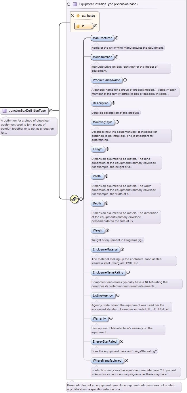
A definition for a piece of electrical equipment used to join pieces of conduit together or to act as a location for making splices. In the model, specific instances of junction boxes are modeled as WirewayBoxes. Note that a JunctionBox may not combine any circuits, a separate DcCombiner element is defined for that purpose in PvSystems.
<xs:complexType name="JunctionBoxDefinitionType"><xs:annotation><xs:documentation>A definition for a piece of electrical equipment used to join pieces of conduit together or to act as a location for making splices. In the model, specific instances of junction boxes are modeled as WirewayBoxes. Note that a JunctionBox may not combine any circuits, a separate DcCombiner element is defined for that purpose in PvSystems.</xs:documentation></xs:annotation><xs:complexContent><xs:extension base="EquipmentDefinitionType"/></xs:complexContent></xs:complexType>
Complex Type DisconnectSwitchDefinitionType
Namespace
http://www.iepmodel.net
Annotations
A definition for a piece of equipment that can disconnect a CircuitConnection. In the model, specific instances of Disconnect switches are modeled as WirewayBoxes.
<xs:complexType name="DisconnectSwitchDefinitionType"><xs:annotation><xs:documentation>A definition for a piece of equipment that can disconnect a CircuitConnection. In the model, specific instances of Disconnect switches are modeled as WirewayBoxes.</xs:documentation></xs:annotation><xs:complexContent><xs:extension base="EquipmentDefinitionType"><xs:sequence><xs:element minOccurs="1" name="DiscoRating" type="xs:integer"><xs:annotation><xs:documentation>Rating in amps for disconnecting an AC or DC circuit.</xs:documentation></xs:annotation></xs:element><xs:element minOccurs="0" name="AcVoltageRating" type="xs:integer"/><xs:element minOccurs="0" name="DcVoltageRating" type="xs:integer"/><xs:element name="SwitchContact" minOccurs="0" type="SwitchContactActionEnumType"><xs:annotation><xs:documentation>The terms pole and throw are also used to describe switch contact variations. The number of "poles" is the number of separate circuits which are controlled by a switch. For example, a "2-pole" switch has two separate identical sets of contacts controlled by the same knob. The number of "throws" is the number of separate positions that the switch can adopt. A single-throw switch has one pair of contacts that can either be closed or open. A double-throw switch has a contact that can be connected to either of two other contacts, a triple-throw has a contact which can be connected to one of three other contacts, etc</xs:documentation></xs:annotation></xs:element><xs:element minOccurs="0" name="Duty" type="SwitchDutyEnumType"/><xs:element minOccurs="0" name="VisibleLock" type="xs:boolean"><xs:annotation><xs:documentation>Does the switch have a visible locking mechnism?</xs:documentation></xs:annotation></xs:element><xs:element minOccurs="0" name="Fusible" type="xs:boolean"><xs:annotation><xs:documentation>Do the switch circuits include fuses?</xs:documentation></xs:annotation></xs:element><xs:element minOccurs="0" name="Fuse" type="FuseType"><xs:annotation><xs:documentation>If the switch includes fuses, this describes the fuses.</xs:documentation></xs:annotation></xs:element></xs:sequence></xs:extension></xs:complexContent></xs:complexType>
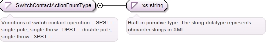
Simple Type SwitchContactActionEnumType
Namespace
http://www.iepmodel.net
Annotations
Variations of switch contact operation.- SPST = single pole, single throw- DPST = double pole, single throw- 3PST = triple pole, single throw- SPDT = single pole, double throw (aka "changover switch")
If the WirewaySegment is a junction box or disconnect switch, this refers to its EquipmentDefinition. A WirewayBox may be a pass through where multiple ConduitSegments are combined into a single ConduitSegment for example. A disconnect switch box may also be modeled as a WirewayBox, provided that the circuit(s) involved are simply disoconnected and not combined in any way. DO NOT use WirewayBox to represent a combiner, or distribution panel.
<xs:complexType name="ConduitSegmentType"><xs:annotation><xs:documentation>A ConduitSegment is any continuous section of electrical conduit of a consistent type.</xs:documentation></xs:annotation><xs:complexContent><xs:extension base="WirewaySegmentType"><xs:sequence><xs:element name="ConduitType" type="TypeOfConduitEnumType" minOccurs="0" maxOccurs="1"/><xs:element name="ConduitDiameter" type="ConduitDiameterEnumType" minOccurs="0" maxOccurs="1"/><xs:element name="ConduitLength" type="xs:double" minOccurs="0"><xs:annotation><xs:documentation>The length in feet of the conduit segment. Values should be rounded up to nearest foot.</xs:documentation></xs:annotation></xs:element><xs:element maxOccurs="2" name="SegmentConnection" type="xs:IDREF" minOccurs="0"><xs:annotation><xs:documentation>The ID Ref for another WirewaySegment or Equipment to which the Coduit segment connects. Conduit is a pipe with 2 ends, so it has a maximum of two WirewaySegments or Equipment to which it connects. Boxes can have many WirewaySegment connections.</xs:documentation></xs:annotation></xs:element></xs:sequence></xs:extension></xs:complexContent></xs:complexType>
<xs:simpleType name="ConduitDiameterEnumType"><xs:annotation><xs:documentation>List of industry standard electrical conduit diameters in inches.</xs:documentation></xs:annotation><xs:restriction base="xs:string"><xs:enumeration value="1/2"/><xs:enumeration value="3/4"/><xs:enumeration value="1"/><xs:enumeration value="1 1/4"/><xs:enumeration value="1 1/2"/><xs:enumeration value="2"/></xs:restriction></xs:simpleType>
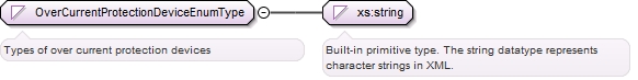
Simple Type OverCurrentProtectionDeviceEnumType
Namespace
http://www.iepmodel.net
Annotations
Types of over current protection devices
Diagram
Type
restriction of xs:string
Facets
enumeration
circuit breaker
enumeration
fuse
enumeration
none
Source
<xs:simpleType name="OverCurrentProtectionDeviceEnumType"><xs:annotation><xs:documentation>Types of over current protection devices</xs:documentation></xs:annotation><xs:restriction base="xs:string"><xs:enumeration value="circuit breaker"/><xs:enumeration value="fuse"/><xs:enumeration value="none"/></xs:restriction></xs:simpleType>
Complex Type MeterDefinitionType
Namespace
http://www.iepmodel.net
Annotations
A device that records the quantity of energy units consumed by the customer.
<xs:complexType name="MeterDefinitionType"><xs:annotation><xs:documentation>A device that records the quantity of energy units consumed by the customer.</xs:documentation></xs:annotation><xs:complexContent><xs:extension base="EquipmentDefinitionType"><xs:sequence><xs:element minOccurs="0" name="Directionality" type="xs:string"><xs:annotation><xs:documentation>Is the meter mono or bi-directional?</xs:documentation></xs:annotation></xs:element><xs:element minOccurs="0" name="MeasurementMechanism" type="xs:string"><xs:annotation><xs:documentation>What type of measurement mechanism does the meter employ? For example, "current transducer" or "inline electro-mechanical"</xs:documentation></xs:annotation></xs:element></xs:sequence></xs:extension></xs:complexContent></xs:complexType>
If the WirewaySegment is a junction box or disconnect switch, this refers to its EquipmentDefinition. A WirewayBox may be a pass through where multiple ConduitSegments are combined into a single ConduitSegment for example. A disconnect switch box may also be modeled as a WirewayBox, provided that the circuit(s) involved are simply disoconnected and not combined in any way. DO NOT use WirewayBox to represent a combiner, or distribution panel.
<xs:attribute name="EquipmentDefinitionIdRef" type="xs:IDREF"><xs:annotation><xs:documentation>If the WirewaySegment is a junction box or disconnect switch, this refers to its EquipmentDefinition. A WirewayBox may be a pass through where multiple ConduitSegments are combined into a single ConduitSegment for example. A disconnect switch box may also be modeled as a WirewayBox, provided that the circuit(s) involved are simply disoconnected and not combined in any way. DO NOT use WirewayBox to represent a combiner, or distribution panel.</xs:documentation></xs:annotation></xs:attribute>
Reference to an instance of the DisconnectSwitch modeled generally as a WirewayBox. A disconnect switch can switch more than one CircuitConnection, so it is defined external to the CircuitConnection.
<xs:attribute name="WirewayBoxIdRef" type="xs:IDREF" use="required"><xs:annotation><xs:documentation>Reference to an instance of the DisconnectSwitch modeled generally as a WirewayBox. A disconnect switch can switch more than one CircuitConnection, so it is defined external to the CircuitConnection.</xs:documentation></xs:annotation></xs:attribute>
<xs:attribute name="ConductorSegmentIdRef" type="xs:IDREF" use="required"><xs:annotation><xs:documentation>ConductorSegment that contains the disconnect switch.</xs:documentation></xs:annotation></xs:attribute>
The ID referring to the equipment in which the OCPD is installed. In most cases, it is the parent Equipment of the CircuitConnection's immediate parent element. For example, if the CircuitConnection is within a StringInverter element, then the circuit breaker within the ElectricalPanel to which the Inverter connects will most like be the referenced OCPD.
<xs:attribute name="EquipmentWhereLocatedIdRef"><xs:annotation><xs:documentation>The ID referring to the equipment in which the OCPD is installed. In most cases, it is the parent Equipment of the CircuitConnection's immediate parent element. For example, if the CircuitConnection is within a StringInverter element, then the circuit breaker within the ElectricalPanel to which the Inverter connects will most like be the referenced OCPD.</xs:documentation></xs:annotation></xs:attribute>
In cases where the CircuitConnection element is used within an EquipmentInstance that does not have a parent element to which the CircuitConnection is assumed to connect, a reference ID can be used to associate this CircuitConnection to another EquipmentInstance elsewhere in a document instance. For example, a PvSystem may have an AcPointOfConnection that uses a new ElectricalPanel as an AC combiner for more than one Inverter. The new electrical panel can be described by an ElectricalPanel element in the PvDesign (which in turn refers to an ElectricalPanelDefinition element).in the AcPointOfConnection's EquipmentWhereConnected element. That ElectricPanel's EnergizingCircuitConnection element may reference another ElectricPanel in an instance of the Project's ExistingElectricalHierarchy element.
<xs:attribute name="EquipmentWhereConnectedIdRef" type="xs:IDREF"><xs:annotation><xs:documentation>In cases where the CircuitConnection element is used within an EquipmentInstance that does not have a parent element to which the CircuitConnection is assumed to connect, a reference ID can be used to associate this CircuitConnection to another EquipmentInstance elsewhere in a document instance. For example, a PvSystem may have an AcPointOfConnection that uses a new ElectricalPanel as an AC combiner for more than one Inverter. The new electrical panel can be described by an ElectricalPanel element in the PvDesign (which in turn refers to an ElectricalPanelDefinition element). in the AcPointOfConnection's EquipmentWhereConnected element. That ElectricPanel's EnergizingCircuitConnection element may reference another ElectricPanel in an instance of the Project's ExistingElectricalHierarchy element.</xs:documentation></xs:annotation></xs:attribute>